1. Network Roles, IP Address and Capacity Planning
Overview
In traditional SDI facilities, signal planning was primarily concerned with router ports, cable routes and tie-lines. In IP facilities, addressing becomes part of the infrastructure design.
Poor IP address planning can result in:
- Difficult expansion projects
- Route summarisation limitations
- Site-to-site connectivity challenges
- SDN integration difficulties
- Operational complexity
A well-designed IPAM strategy allows facilities to grow from tens to thousands of devices without requiring re-addressing. When designing an IP broadcast facility, it is important for an organisation to adequately plan and manage the IP addresses of their infrastructure. This document provides some key information on how to understand:
- The various network roles that are required for a modern IP broadcast facility
- How to plan an IP address schema to allow for:
- Increases in network capacity
- Increasing the number of IP broadcast facilities within an organisation
- Using appropriate IP address ranges and subnet masks
- The benefits of adopting Lawo's IPAM structure
This document is applicable for audio and media infrastructure integrations. It assumes the reader is familiar with basic networking concepts, such as:
- Network traffic types: unicast, multicast and broadcast
- IP addresses
Assessing Key Network Requirements
Understanding Network Roles
A typical IP broadcast facility will require at least four fabrics which perform different roles:
- Base
- e.g. switch hardware and PTP GMCs communication
- Broadcast Control / Management
- e.g. HOME and/or vsmStudio control and configuration data communication
- Red Streaming Media
- e.g. ST2110, RAVENNA audio, metadata, PTP, video traffic, etc.
- Blue Streaming Media
- e.g. ST2110, RAVENNA audio, metadata, PTP, video traffic, etc.
A network fabric consists of multiple devices (switches, servers, control panels etc.) that are interconnected in a highly scalable, resilient, and efficient way. In addition to the fabrics listed above, some customers may require additional network fabrics, for example:
- Purple Streaming Media
- Typically used for devices that support 2022-7 via a single interface
- e.g. Riedel MediorNet FusioN (Embrionix emFUSION)
- Typically used for devices that support 2022-7 via a single interface
- Low Bandwidth Streaming Media
- e.g. NDI, SRT etc.
- Out-of-Band Management (OOB)
- A dedicated network used for managing IT infrastructure independently from the main data or production network
- e.g. network switch management ports, server 'lights out management' ports etc.
- A dedicated network used for managing IT infrastructure independently from the main data or production network
Understanding Device Count and Network Scaling
Most customers new to IP-based broadcasting usually start by designing a small facility, typically consisting of less than 50 endpoints in the Red/Blue streaming media fabrics. Once they have gained experience and are comfortable with operating and managing their infrastructure, they often choose to add capacity to the existing facility, build another IP facility, or both. At this point, it is important to understand some key IPAM best practices:
- IP addresses within a single facility must be unique
- e.g. two endpoints cannot share the same IP address in any fabric — this creates an IP address conflict and traffic cannot be sent to endpoints reliably
- Avoid designing an IP address 'template' and use the same IP addresses across multiple facilities
- e.g. two OB vans with the same duplicated VLANs/networks and IP address structure
- This approach has two major disadvantages:
- It can lead to building large Layer 2 failure domains
- It can complicate or even prevent multiple facilities from communicating with each other in the future
- e.g. OB van to OB van operations
Understanding the minimum number of streaming media endpoints a facility will need to support and adding 20%, is a good indicator for the amount of IP addresses that will be required. Lawo advises that customers assume and plan for growth from the very beginning. This could be the original facility increasing network capacity by adding more switches and endpoints, or building multiple new IP facilities of any size. For this reason, Lawo encourages the use of a hierarchical addressing scheme for all network fabrics:
- Allocate a unique IP range to each IP facility
- A facility's IP range can be divided into smaller ranges by a process called subnetting
- Each fabric is assigned a unique range of IP addresses
- Each fabric in the IP facility performs a specific network role
- Each fabric's IP address range can be subnetted further into smaller ranges
- Each fabric in the IP facility performs a specific network role
- Each fabric is assigned a unique range of IP addresses
- A facility's IP range can be divided into smaller ranges by a process called subnetting
By using this method of organising and allocating IP addresses, there is IP space for each fabric to accommodate future devices and facilities. Additionally, a hierarchical addressing scheme:
- Ensures unique IP allocations to each facility
- Ensures unique IP allocations to each fabric
- Ensures unique IP allocations to each endpoint
- Enables site-to-site connectivity and communication
- Prevents routing conflicts and connectivity issues between IP facilities
Understanding IP Address Ranges and Subnetting
Lawo encourages customers to use private IP address ranges as defined in RFC 1918 (IPv4) and RFC 4193 (IPv6. They are reserved for internal network use and cannot be routed over the Internet. Using them correctly ensures efficient network management, security, and scalability.
| IP ADDRESS RANGE | CIDR NOTATION | NO. ADDRESSES |
|---|---|---|
| 10.0.0.0 - 10.255.255.255 | 10.0.0.0/8 | 16.7 million |
| 172.16.0.0 - 172.31.255.255 | 172.16.0.0/12 | 1 million |
| 192.168.0.0 - 192.168.255.255 | 192.168.0.0/16 | 65,536 |
Private IPs must be NATed (Network Address Translated) to communicate over the Internet.
Lawo advises customers to provide their own private IP address range for broadcast operations, for example, a /16 IP address range:
| CIDR NOTATION | 10.1.0.0/16 |
| IP ADDRESS RANGE | 10.1.0.0 - 10.1.255.255 |
Lawo provides the following per-octet IP address structure as a foundation:
| 1st OCTET | 2nd OCTET | 3rd OCTET | 4th OCTET | |
|---|---|---|---|---|
| Network | IP Facility | Fabric / Switch # | Host | |
| 10 | 1 | 0-255 | 0-255 | |
Customers planning to build multiple IP broadcast facilities should consider using a unique /16 IP range per IP facility. This can be achieved by assigning a unique number in the second octet of an IP range. The benefits to this approach include:

Use of 2nd Octet
- Makes it easier to identify individual IP facilities within an organisation.
- Makes it potentially easier to move equipment between IP facilities as only the second octet in the IP address may need to change.
| FACILITY NAME | 1st OCTET | 2nd OCTET | 3rd OCTET | 4th OCTET |
|---|---|---|---|---|
| Network | Facility ID | Fabric | Host | |
OB Van #1 | 10 | 1 | 0-255 | 0-255 |
OB Van #2 | 10 | 2 | 0-255 | 0-255 |
Once an appropriate private IP range has been determined, the process of subnetting (or creating smaller blocks of IP ranges) and assigning them to the individual network fabrics can begin. Selecting an appropriate subnet mask avoids wasting IP addresses and ensures room for future expansion. Below is a table of common subnet masks:
| # of ENDPOINTS | CIDR NOTATION | SUBNET MASK | ADDRESSES |
|---|---|---|---|
| 1 | /32 | 255.255.255.255 | 1 |
| 2 | /31 | 255.255.255.254 | 2 |
| 2 | /30 | 255.255.255.252 | 4 |
| 2-6 | /29 | 255.255.255.248 | 8 |
| 7-14 | /28 | 255.255.255.240 | 16 |
| 15-30 | /27 | 255.255.255.224 | 32 |
| 31-62 | /26 | 255.255.255.192 | 64 |
| 63-126 | /25 | 255.255.255.128 | 128 |
| 127-254 | /24 | 255.255.255.0 | 256 |
| 255-510 | /23 | 255.255.254.0 | 512 |
| 511-1,022 | /22 | 255.255.252.0 | 1,024 |
| 1,023-2,046 | /21 | 255.255.248.0 | 2,048 |
| 2,047-4,094 | /20 | 255.255.240.0 | 4,096 |
| 4,095-8,190 | /19 | 255.255224.0 | 8,192 |
| 8,191-16,382 | /18 | 255.255.192.0 | 16,384 |
| 16,383-32,766 | /17 | 255.255.128.0 | 32,768 |
| 32,767-65,534 | /16 | 255.255.0.0 | 65,536 |
Differences between /30 and /31 subnets
- /30 and /31 subnets both support two endpoints and are typically used for point-to-point links. However, a /31 subnet does not have a network or a broadcast address. Traditionally, point-to-point links needed a /30 subnet, 'wasting' two IPs (network and broadcast). RFC 3021 allows /31 subnets for point-to-point links as a broadcast function is not necessary.
- /30 subnets
- Support legacy and modern equipment
- Support DHCP — suitable for dynamic addressing of endpoints
- Suitable for small, private networks and point to-point links
- Not suitable for saving IP addresses in projects with very limited IPv4 address space
- /31 subnets
- Do not support some legacy equipment
- Do not support DHCP as a a broadcast address is requird
- Suitable for point-to-point links only
- Suitable for saving IP addresses in projects with very limited IPv4 address space
A /31 subnet provides two usable IPv4 addresses for a point-to-point connection, as defined in RFC 3021. Both connected devices must support /31 addressing
Static IP addressing is generally preferred for routed infrastructure links to ensure predictable connectivity and simplify troubleshooting. DHCP may be suitable for other network roles, depending on the device capabilities and operational requirements
The third octet in the IP address range can be appropriately subnetted and assigned to the network fabrics:
| FACILITY SIZE | 1st OCTET | 2nd OCTET | 3rd OCTET | 4th OCTET | CIDR NOTATION |
|---|---|---|---|---|---|
| Network | Facility ID | Fabric | Host | ||
Compatible with | 10 | 1 | 0-127 (BCAST-CTRL) 128-159 (RED-MEDIA) 160-191 (BLUE-MEDIA) 192-207 (PURPLE-MEDIA) 208-223 (NDI-SRT-MEDIA) 224-239 (BASE-NET) 240-255 (OOB-MGMT) | 0-255 | 10.1.0.0/17 10.1.128.0/19 10.1.160.0/19 10.1.192.0/20 10.1.208.0/20 10.1.224.0/20 10.1.240.0/20 |
Understanding VLANs (Logical Segmentation)
For the majority of streaming media LVN fabrics, VLANs are not implemented. Instead, routed interfaces assigned to /30 networks are favoured. In Broadcast Control / Management fabrics however, VLANs can be paired with subnets to:
- Reduce the size of the failure domain
- e.g. the amount of devices that will be affected in the event of network disruption
- Reduce the size of the broadcast domain and improve efficiency
- Improve network performance and security
Consider the Broadcast Control / Management fabric:
- For a VLAN that consists of 2-3 devices (e.g. a HOME or vsmStudio server cluster), a /29 subnet mask (6 devices) is more appropriate than a /24 subnet mask (254 devices) as it minimizes wasted IP addresses and creates very small networks dedicated to devices of a similar type
- For a VLAN that consists of 60 vsmStudio control panels, a /26 subnet mask (64 devices) is more appropriate than a /24 subnet mask (254 devices) as it also minimizes wasted IP addresses and creates small networks dedicated to devices of a similar type
There is no single 'best practice' to allocating VLANs in a Broadcast Control / Management fabric, however there are two good strategies to be aware of:
- A VLAN per device type
- This method subnets the IP address range assigned to the Broadcast Control / Management fabric and creates networks and VLANs based on the devices by type:
- VLAN 10: Engineering terminals
- VLAN 11: HOME servers
- VLAN 21: vsmStudio servers
- VLAN 22: vsmGadget servers
- VLAN 23: vsmStudio control panels
- VLAN 24: vsmStudio control panels
- VLAN 31: XCS servers
- VLAN 41: Audio consoles (mc2)
- VLAN 42: Radio consoles (crystal, diamond)
- VLAN 51:..edge blades
- VLAN 61: HOME Apps servers
- VLAN 71: A__UHD Cores
- VLAN 81: Power Cores
- VLAN 91: A__line devices
- VLAN 101: Workspaces
- VLAN 111: Timing & synchronisation
- A VLAN per location/application
- This method subnets the IP address range assigned to the Broadcast Control / Management fabric and creates networks and VLANs based on the devices that are grouped by their application or location — e.g.
- VLAN 11: Studio A (audio): A__UHD Cores, XCS servers, A__line devices, mc2 consoles
- This method subnets the IP address range assigned to the Broadcast Control / Management fabric and creates networks and VLANs based on the devices that are grouped by their application or location — e.g.
The 'VLAN per location/application' method is particularly applicable to audio infrastructure customers who wish to make use of Lawo's resource sharing feature, whereby A__UHD Cores and XCS servers can be logically paired together to provide multiple virtual mixing facilities
Customers can also choose to use elements of both approaches in their designs.
Example LVN IPAM Structure
For customers new to IP in general, Lawo can provide IPAM guidelines which enable customers to:
- Plan for growth at the start of their IP journey
- Optimize IP address allocation
- Ensure unique IP ranges are allocated to each facility
- Ensure unique IP ranges are allocated to each fabric
- Ensure unique IP ranges are allocated to each endpoint
- Enable facility-to-facility connectivity and communication
- Accommodate from small to large facilities
- Provide consistent IPAM information making documentation easier to maintain
- Easily implement network security features
Example LVN Fabrics
The LVN IPAM structure example implements the following fabrics:
| FABRIC | BCAST-CTRL-NET | RED-MEDIA-NET | BLUE-MEDIA-NET | PURPLE-MEDIA-NET | LB-STREAM-NET | BASE-NET | OOB-NET |
|---|---|---|---|---|---|---|---|
| DESCRIPTION | Control and Management e.g. vsmStudio, HOME | Streaming Media e.g. ST2110, RAVENNA | Streaming Media e.g. ST2110, RAVENNA | Streaming Media e.g. ST2110, RAVENNA | Low Bandwidth Streaming Media e.g. NDI,SRT, JPEG-XS | Loopback interfaces | Lights Out Management |
Example LVN Unicast Address Ranges
Customers are advised to allocate a unique IP address range to each IP broadcast facility themselves. In this example, the customer has chosen 10.1.0.0/16:
| NETWORK | 10.1.0.0/16 | ||||||
|---|---|---|---|---|---|---|---|
| FABRIC | BCAST-CTRL-NET | RED-MEDIA-NET | BLUE-MEDIA-NET | PURPLE-MEDIA-NET | LB-STREAM-NET | BASE-NET | OOB-NET |
| DESCRIPTION | Control and Management e.g. vsmStudio, HOME | Streaming Media e.g. ST2110, RAVENNA | Streaming Media e.g. ST2110, RAVENNA | Streaming Media e.g. ST2110, RAVENNA | Low Bandwidth Streaming Media e.g. NDI,SRT, JPEG-XS | Loopback interfaces | Lights Out Management |
The 10.1.0.0/16 IP address range can then be subnetted into smaller IP ranges and assigned to the fabrics.
| NETWORK | 10.1.0.0/16 | ||||||
|---|---|---|---|---|---|---|---|
| FABRIC | BCAST-CTRL-NET | RED-MEDIA-NET | BLUE-MEDIA-NET | PURPLE-MEDIA-NET | LB-STREAM-NET | BASE-NET | OOB-NET |
| DESCRIPTION | Control and Management e.g. vsmStudio, HOME | Streaming Media e.g. ST2110, RAVENNA | Streaming Media e.g. ST2110, RAVENNA | Streaming Media e.g. ST2110, RAVENNA | Low Bandwidth Streaming Media e.g. NDI,SRT, JPEG-XS | Loopback interfaces | Lights Out Management |
| SUBNET | 10.1.0.0/17 | 10.1.128.0/19 | 10.1.160.0/19 | 10.1.192.0/20 | 10.1.208.0/20 | 10.1.224.0/20 | 10.1.240.0/20 |
| IP ADDRESS RANGE | 10.1.0.0 - 10.1.127.255 | 10.1.128.0 - 10.1.159.255 | 10.1.160.0 - 10.1.191.255 | 10.1.192.0 - 10.1.207.255 | 10.1.208.0 - 10.1.208.255 | 10.1.224.0 - 10.1.239.255 | 10.1.240.0 - 10.1.255.255 |
| # of ENDPOINTS | 2000+ | Up to 2,048 | Up to 2,048 | Up to 1,024 | 1024+ | - | - |
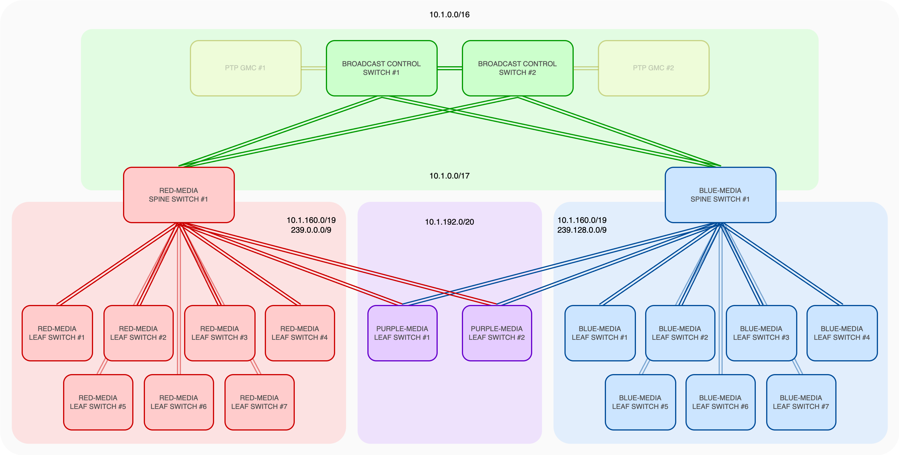
BCAST-CTRL-NET Leaf switches do not explicitly require IP addresses and therefore are not shown in the diagram
Example LVN Multicast Address Ranges
Lawo advises customers to use the 'Administratively Scoped' (private) multicast address range 239.0.0.0 - 239.255.255.255. This range is equivalent to the unicast private IPs (RFC 1918) previously mentioned and is used for local multicast within an organization. The range can be subnetted into two equal ranges and provides over 8.3 million multicast addresses to each Streaming Media fabric:
| FABRIC | IP RANGE | CIDR NOTATION | ADDRESSES |
|---|---|---|---|
| Red | 239.0.0.0 - 239.127.255.255 | 239.0.0.0/9 | 8,388,608 |
| Blue | 239.128.0.0 - 239.255.255.255 | 239.128.0.0/9 | 8,388,608 |
Customers can also choose to make distinguishing between the Red and Blue streaming media networks easier by changing the starting point of the second octet, for example:
| FABRIC | IP RANGE |
|---|---|
| Red | 239.30.0.0 - 239.127.255.255 |
| Blue | 239.130.0.0 - 239.255.255.255 |
Multicast Aliasing
In an Ethernet network, multicast IP addresses (224.0.0.0 to 239.255.255.255) need to be mapped to MAC addresses so that network devices can properly forward packets at Layer 2. IPv4 multicast addresses are mapped to MAC addresses in the following way:
- The first 25 bits of the multicast MAC address are fixed: 01:00:5E
- The next 23 bits of the MAC address come from the last 23 bits of the multicast IP address
Therefore, multiple different multicast IP addresses can map to the same MAC address as 23 bits of the 32-bit IP address are used. The 239.0.0.0 range assigned to the Red Streaming Media fabric has the same MAC address as the 239.128.0.0 range assigned to the Blue Streaming Media fabric, however this is not a problem because the LVN IPAM structure avoids multicast aliasing by implementing the following measures:
- Routing multicast at Layer 3 (instead of relying only on Layer 2 forwarding) ensures that IP addresses are respected rather than just MAC addresses
- Multicast routing protocols like PIM Sparse Mode (PIM-SM) prevent multicast aliasing by using explicit join requests
- The endpoints are separated by L3 boundaries e.g. /30 networks on each routed interface
- The 239.0.0.0 and 239.128.0.0 ranges are in separate fabrics
Multicast Aliasing and Layer 3 Routing
- IPv4 multicast aliasing occurs when different multicast group addresses map to the same Ethernet multicast MAC address. This mapping is inherent to IPv4 multicast over Ethernet and is not eliminated by Layer 3 routing or PIM
- Layer 3 multicast routing maintains forwarding state based on IP multicast groups and, where applicable, source addresses. This allows multicast traffic to be routed selectively between subnets according to the multicast routing state
- Separating media networks into distinct Layer 3 domains can help contain the effects of multicast aliasing by limiting the Layer 2 forwarding domain in which a MAC address collision may occur. However, the forwarding behaviour within each domain remains dependent on the capabilities and implementation of the network switches
AIS Multicast Organization (audio-only)
| 1st OCTET | 2nd OCTET | 3rd OCTET | 4th OCTET | |
|---|---|---|---|---|
| Location | Fabric & Signal Type | Flow Essence | Flow Number | |
| 239 | 0-127 128-255 | 0-255 | 0-255 | |
| 0-63 | 8ch | |||
| 64-127 | 16ch | |||
| 128-191 | 48ch | |||
| 192-255 | 64ch | |||
Lawo encourages customers to use the second octet in a sequential order rather than picking numbers ad-hoc
MIS Multicast Organization
| 1st OCTET | 2nd OCTET | 3rd OCTET | 4th OCTET | |
|---|---|---|---|---|
| Location | Fabric & Signal Type | Flow Essence | Flow Number | |
| 239 | 0-127 128-255 | 0-255 | 0-255 | |
0 = HD 1 = 3G 2 = UHD 16 = Audio-only 113 = .edge 1/4 proxy 114 = .edge 1/16 proxy 115 = .edge 1/64 proxy 128 = HD 129 = 3G 130 = UHD 144 = Audio-only 241 = .edge 1/4 proxy 242 = .edge 1/16 proxy 243 = .edge 1/64 proxy | 0-31 | Video | ||
| 32-63 | Audio 1 (8ch) | |||
| 64-95 | Audio 2 (8ch) | |||
| 96-127 | Audio 3 (64ch) | |||
| 128-159 | Audio 4 (64ch) | |||
| 160-191 | ANC 1 (-40) | |||
| 192-223 | ANC 2 (-41) | |||
Should a customer wish to evolve a facility and integrate an SDN controller in the future, the example LVN IPAM structure for unicast and multicast above is also compatible with Arista's MCS and Cisco's NDFC/NBM SDN controllers.