2. Fabrics, Prefixes, Subnetting and Summarisation
Overview
It is important for an organization designing an IP broadcast facility to adequately plan and manage the IP addresses of their infrastructure. This document describes the technical details behind the example LVN IPAM structure and provides information on how to understand:
- The purpose of IP prefixes and assigning them to the network fabrics
- Subnetting IP prefixes — the process of dividing a large pool of addresses (a prefix) into smaller, more manageable subnetworks (subnets)
- The purpose of summarization
- Easy to understand, predict and configure routes to networks by using route summarization
- Reducing the number of networks/routes a switch advertises to its neighbor
- Easy to understand, predict and configure routes to networks by using route summarization
By following the LVN IPAM example guidelines, customers may allocate IP addresses, allowing for:
- An individual facility to add capacity/horizontally increase in scale in the future
- The planning of multiple facilities to transition from legacy baseband to IP infrastructure
- The inter-connectivity of sites and facilities (e.g. studio-to-studio, studio-to-truck, truck-to-truck, etc.)
- The transition from non-SDN controlled Streaming Media network(s) to SDN controlled Streaming Media network(s) while also allowing for:
- L3-PIM Leaf switches
- vsmShare
This document is applicable for AIS and MIS integrations.
IP Prefixes
IP Prefixes are used to create an aggregation or pool of IPv4 or IPv6 addresses for the various networks that make up an IP broadcast facility. The network address and subnet mask are expressed in CIDR notation. Currently, Lawo makes use of the IPv4 addressing system. The table below illustrates how a pool of IP addresses (a prefix) can be allocated to multiple fabrics at a parent level:
Example Parent IP Prefixes
| FABRIC | BCAST-CTRL-NET | RED-MEDIA-NET | BLUE-MEDIA-NET | PURPLE-MEDIA-NET | LB-STREAM-NET | BASE-NET | OOB-NET |
|---|---|---|---|---|---|---|---|
| USED FOR | Control and Management e.g. VSM, HOME | Streaming Media e.g. ST2110, RAVENNA | Streaming Media e.g. ST2110, RAVENNA | Streaming Media e.g. ST2110, RAVENNA | Low Bandwidth Streaming Media e.g. NDI,SRT, JPEG-XS | Switch loopback interfaces | Lights Out Management |
| IP PREFIX | 10.1.0.0/17 | 10.1.128.0/19 | 10.1.160.0/19 | 10.1.192.0/20 | 10.1.208.0/20 | 10.1.224.0/20 | 10.1.240.0 - 10.1.255.255 |
ADDRESSES | 32,768 | 8,192 | 8,192 | 4,096 | 4,096 | 4,096 | 4,096 |
ADDRESS RANGE | 10.1.0.0 - 10.1.127.255 | 10.1.128.0 - 10.1.159.255 | 10.1.160.0 - 10.1.191.255 | 10.1.192.0 - 10.1.207.255 | 10.1.208.0 - 10.1.223.255 | 10.1.224.0 - 10.1.239.255 | 10.1.240.0 - 10.1.255.255 |
| REQUIREMENT | Mandatory | Mandatory | Optional | Optional | Optional | Mandatory | Optional |
Once parent level IP prefixes have been established, the pool of addresses can be divided or 'subnetted' into child prefixes for further designation:
Example Child IP Prefixes
| FABRIC | BCAST-CTRL-NET | RED-MEDIA-NET | BLUE-MEDIA-NET | PURPLE-MEDIA-NET | BASE-NET |
|---|---|---|---|---|---|
| PARENT PREFIX | 10.1.0.0/17 | 10.1.128.0/19 | 10.1.160.0/19 | 10.1.192.0/20 | 10.1.224.0/20 |
CHILD PREFIX A | 10.1.0.0/24 | 10.1.128.0/24 | 10.1.160.0/24 | 10.1.192.0/24 | 10.1.224.0/27 |
ADDRESS RANGE | 10.1.0.0 - 10.1.0.255 | 10.1.128.0 - 10.1.128.255 | 10.1.160.0 - 10.1.160.255 | 10.1.192.0 - 10.1.192.255 | 10.1.224.0 - 10.1.224.31 |
ALLOCATION | ENGINEERS | RED-SPINE-01 | BLUE-SPINE-01 | PURPLE-LEAF-01 | LOOPBACK-INT |
ADDRESSES | 256 | 256 | 256 | 256 | 32 |
| CHILD PREFIX B | 10.1.1.0/29 | 10.1.129.0/24 | 10.1.161.0/17 | 10.1.193.0/24 | 10.1.224.32/27 |
| ADDRESS RANGE | 10.1.1.0 - 10.1.1.7 | 10.1.128.0 - 10.1.255.255 | 10.1.161.0 - 10.1.161.255 | 10.1.193.0 - 10.1.193.255 | 10.1.224.32 - 10.1.224.63 |
| ALLOCATION | HOME-CLUSTER | RED-LEAF-01 | BLUE-LEAF-01 | PURPLE-LEAF-02 | MLAG-INT |
| ADDRESSES | 8 | 256 | 256 | 256 | 32 |
This process can be repeated in order to create further child prefix subnets, for example allocating specific address spaces per Studio/OB Truck:
| FABRIC | BCAST-CTRL-NET | RED-MEDIA-NET | BLUE-MEDIA-NET | PURPLE-MEDIA-NET | BASE-NET |
|---|---|---|---|---|---|
| PARENT PREFIX | 10.1.0.0/17 | 10.1.128.0/19 | 10.1.160.0/19 | 10.1.192.0/20 | 10.1.224.0/20 |
CHILD PREFIX A | 10.1.0.0/24 | 10.1.128.0/24 | 10.1.160.0/24 | 10.1.192.0/24 | 10.1.224.0/27 |
ADDRESS RANGE | 10.1.0.0 - 10.1.0.255 | 10.1.128.0 - 10.1.128.255 | 10.1.160.0 - 10.1.160.255 | 10.1.192.0 - 10.1.192.255 | 10.1.224.0 - 10.1.224.31 |
ALLOCATION | ENGINEERS | RED-SPINE-01 | BLUE-SPINE-01 | PURPLE-LEAF-01 | LOOPBACK-INT |
ADDRESSES | 256 | 256 | 256 | 256 | 32 |
| CHILD PREFIX B | 10.1.1.0/29 | 10.1.129.0/24 | 10.1.161.0/17 | 10.1.193.0/24 | 10.1.224.32/27 |
| ADDRESS RANGE | 10.1.1.0 - 10.1.1.7 | 10.1.129.0 - 10.1.129.255 | 10.1.161.0 - 10.1.161.255 | 10.1.193.0 - 10.1.193.255 | 10.1.224.32 - 10.1.224.63 |
| ALLOCATION | HOME-CLUSTER | RED-LEAF-01 | BLUE-LEAF-01 | PURPLE-LEAF-02 | MLAG-INT |
| ADDRESSES | 8 | 256 | 256 | 256 | 32 |
| CHILD PREFIX C | 10.1.1.8.0/29 | 10.1.130.0/24 | 10.1.162.0/24 | 10.1.194.0/24 | 10.1.224.128/26 |
| ADDRESS RANGE | 10.1.1.8 / 10.1.1.15 | 10.1.130.0 - 10.1.130.255 | 10.1.162.0 - 10.1.162.255 | 10.1.194.0 - 10.1.194.255 | 10.1.224.64 - 10.1.224.127 |
| ALLOCATION | VSM-CLUSTER | RED-LEAF-02 | BLUE-LEAF-02 | PURPLE-LEAF-03 | RED-UPLINKS |
| ADDRESSES | 8 | 256 | 256 | 256 | 64 |
| CHILD PREFIX D | 10.1.1.128.0/25 | 10.1.131.0/24 | 10.1.163.0/17 | 10.1.195.0/24 | 10.1.224.128/28 |
| ADDRESS RANGE | 10.1.1.128 - 10.1.1.255 | 10.1.131.0 - 10.1.131.255 | 10.1.163.0 - 10.1.163.255 | 10.1.195.0 - 10.1.195.255 | 10.1.224.128 - 10.1.224.143 |
| ALLOCATION | VSM-PANELS | RED-LEAF-03 | BLUE-LEAF-03 | PURPLE-LEAF-04 | BCAST-CTRL-UPLINKS |
| ADDRESSES | 128 | 256 | 256 | 256 | 16 |
Summarisable Routes
Lawo encourages the use of IP prefixes for all fabrics that can be easily summarized. Route summarization is a method to reduce multiple routing table entries by using a single statement. It is often used for representing IPv4 address prefixes. Below is an example statement that could be configured on a Broadcast Control / Management switch so that HOME can access devices attached to all switches in the streaming media networks via in-band communication:
Example Use-case of Summarized Routes
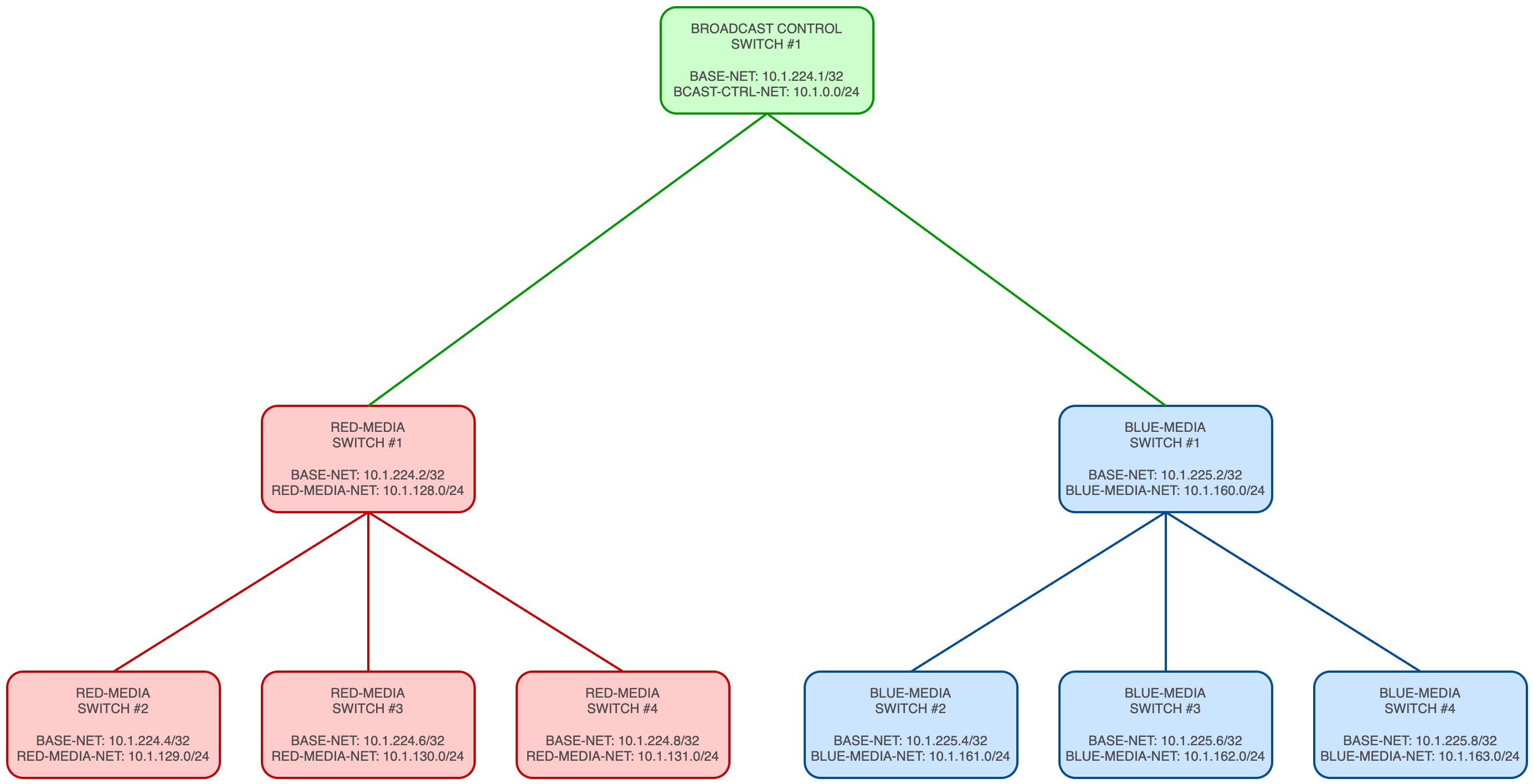
| REMOTE NETWORKS | USING MULTIPLE ROUTING STATEMENTS ON BCAST-CTRL SWITCH | REMOTE NETWORKS | USING SUMMARIZED ROUTE STATEMENTS ON BCAST-CTRL SWITCH |
|---|---|---|---|
| RED-MEDIA SWITCH #1 | ip route 10.1.128.0 255.255.255.0 10.1.224.2 | RED-MEDIA | ip route 10.1.128.0 255.255.252.0 10.1.224.2 |
| RED-MEDIA SWITCH #2 | ip route 10.1.129.0 255.255.255.0 10.1.224.2 | BLUE-MEDIA | ip route 10.2.160.0 255.255.252.0 10.1.225.2 |
| RED-MEDIA SWITCH #3 | ip route 10.1.130.0 255.255.255.0 10.1.224.2 | ||
| RED-MEDIA SWITCH #4 | ip route 10.1.131.0 255.255.255.0 10.1.224.2 | ||
| BLUE-MEDIA SWITCH #1 | ip route 10.1.160.0 255.255.255.0 10.1.225.2 | ||
| BLUE-MEDIA SWITCH #2 | ip route 10.1.161.0 255.255.255.0 10.1.225.2 | ||
| BLUE-MEDIA SWITCH #3 | ip route 10.1.162.0 255.255.255.0 10.1.225.2 | ||
| BLUE-MEDIA SWITCH #4 | ip route 10.1.163.0 255.255.255.0 10.1.225.2 |

Route Summarization
Summarisation is often employed to make routing tables smaller, in addition to the redistribution of routes between routing protocols such as BGP and OSPF. It is also easier to manipulate these routes using route-maps, prefix-list, access-list, etc., for granular control/tuning, e.g. on a Purple switch, block BLUE multicasts from egressing links to RED switches. Additionally, making multicast streams summarizable based on essence types makes it easier to:
- Identify streams during troubleshooting
- Configure multicast boundaries
- Configure PIM Rendezvous Points (RPs) based on different multicast ranges
- Configure flow policies when using SDN Controllers
Base Network Addressing
The Base network refers to the physical network infrastructure that forms the foundation which the remaining networks are built on:
- e.g. the physical switches and hardware that make up the Broadcast Control / Management, Streaming Media networks and PTP/NTP infrastructure forwarding packets based on IPv4 addresses and routing protocols
- The BASE-NET is the specific IP prefix allocated for assigning the physical PTP GMC interfaces, switch hardware and uplink interfaces with IP addresses
The subsequent networks are logically configured alongside the physical BASE-NET:
- e.g. the Broadcast Control / Management and Streaming Media networks
- The BCAST-CTRL-NET, RED-MEDIA-NET, BLUE-MEDIA-NET and PURPLE-MEDIA-NET are the specific IP prefixes allocated for assigning the end point devices network interfaces with IP addresses
Provisioning and implementing an IP prefixes for Base network enables the customer to implement technologies such as virtualization and virtual private networks (VPNs) in the future. Technologies such as Virtual Extensible LAN (VXLAN) can enable devices to span a Layer 2 network across remote networks via the Underlay. This can be particularly useful when intercom systems (which typically do not work well in a Layer 3 routed network) are required to be in the same Layer 2 network, but are located in geographically different facilities.
Loopback Addressing
A loopback interface is a virtual, logical interface that is always in an 'up' or active state and does not depend on a physical port. It is assigned a single /32 IP address and is commonly used for network stability, management, and routing purposes. A switch can be configured to have multiple loopback interfaces.

Loopback Addressing
Loopback interfaces in the Base network are assigned an IP address with a /32 subnet mask:
- e.g.
- 10.1.224.1/32
- 10.1.224.2/32
- 10.1.224.3/32
- etc.
Uplink Addressing (point-to-point)
Uplink interfaces are physical ports designated for interconnecting switches together. They are typically assigned the second available IP address from a /30 subnet, the first available IP address is assigned to the switch interface. A switch will typically have multiple uplink interfaces connected.
Uplink Addressing
Uplink interfaces in the Base network are assigned an IP address with a /30 subnet mask:
- e.g.
- 10.1.224.65/30
- 10.1.224.69/30
- 10.1.224.73/30
- etc.

/31 Uplink Addressing
While /31 masks can also be used, this should be avoided if 'dynamic stagebox' addressing via DHCP is desired by the customer
Broadcast Control / Management Network Addressing
Lawo recommends to logically segment the IP prefix assigned to the BCAST-CTRL fabric by using VLANs paired with subnets to:
VLANs
- ✅ Reduce the size of the failure domain
- e.g. the number of devices that will be affected in the event of network disruption
- ✅ Reduce the size of the broadcast domain and improve efficiency
- ✅ Improve network performance and security
There is no single 'best practice' for allocating VLANs in a Broadcast Control / Management fabric, however there are two good viewpoints to be aware of:
- A VLAN per device type
- This method subnets the IP address range assigned to the Broadcast Control / Management fabric and makes networks and VLANs based on the devices by type:
- VLAN 11: HOME servers
- VLAN 12: vsmStudio servers
- VLAN 13: vsmStudio control panels
- VLAN 14: .edge blades
- VLAN 15: HOME Apps servers
- VLAN 16: A__UHD Cores
- VLAN 17: Power Cores
- VLAN 18: A__line devices
- VLAN 19: Audio consoles
- VLAN 20: Radio consoles
- This method subnets the IP address range assigned to the Broadcast Control / Management fabric and makes networks and VLANs based on the devices by type:
- A VLAN per location/application
- This method subnets the IP address range assigned to the Broadcast Control / Management fabric and makes networks and VLANs based on the devices that a grouped by their application or location — e.g.
- VLAN 11: Studio A (audio): A__UHD Cores, XCS servers, A__line devices, mc2 consoles
- This method subnets the IP address range assigned to the Broadcast Control / Management fabric and makes networks and VLANs based on the devices that a grouped by their application or location — e.g.
Customers can also choose to use elements of both approaches in their designs.
Resource Sharing
The 'VLAN per location/application' method is particularly applicable to audio infrastructure customers who wish to make use of Lawo's resource sharing feature, whereby A__UHD Cores and XCS servers can be logically paired together to provide multiple virtual mixing facilities
Below is a list of best practices to consider when designing a VLAN structure for the Broadcast Control / Management fabric:
BCAST-CTRL LVN Recommendations
- ✅ In Layer 2 Spine-Leaf Broadcast Control / Management networks, configure the BCAST-CTRL spine switches to be the Spanning-Tree Protocol primary/root bridge for each BCAST-CTRL VLAN
- ✅ Configure the first/lowest IP address in a given BCAST-CTRL subnet as the VLANs gateway address (IGMP Snooping querier election is based on 'lowest IP address wins')
- Typically assigned to a Switch Virtual Interface (SVI)
- ✅ Reserve the first three IP addresses in each BCAST-CTRL VLAN/subnet when using switches that implement MLAG or vPC pairing for routing redundancy protocols
- ✅ Configure an IGMP Snooping querier on each BCAST-CTRL VLAN to control multicast discovery mechanisms
- ✅ Disable PTP on BCAST-CTRL access interfaces (Power Core does not like it)
It is common for customers to request the Broadcast Control / Management network connect to the corporate IT network, sometimes via a firewall. This should be achieved by employing static routes to the customer's network via L3 routed interfaces, however, L2 trunk/access ports can also be used.
Streaming Media Network Addressing
High Bandwidth e.g. SMPTE ST2110
The majority of LVNs employ the use of Layer 3 /30 routed interfaces for connecting endpoints to the Streaming Media fabrics. A /30 network comprises four IP addresses:
- Network address
- Host/endpoint address (switch interface)
- Host/endpoint address (device interface)
- Broadcast address
e.g.
| FABRIC | RED-MEDIA-NET | BLUE-MEDIA-NET |
|---|---|---|
| USE | Streaming Media e.g. ST2110, RAVENNA | Streaming Media e.g. ST2110, RAVENNA |
| NETWORK ADDRESS | 10.1.128.0/30 | 10.1.160.0/30 |
HOST ADDRESS | 10.1.128.1 | 10.1.160.1 |
HOST ADDRESS | 10.1.128.2 | 10.1.160.2 |
BROADCAST ADDRESS | 10.1.128.3 | 10.1.160.3 |
The benefits of using this approach to managing IP addresses in Streaming Media networks are:
- LVNs use PIM (Protocol-Independent Multicast) to establish multicast communication between switches in the same Streaming Media fabric
- The switches are PIM neighbors and communicate over point-to-point links, a /30 subnet (2 usable IPs) is the most efficient way to allocate addresses
- /30 networks minimise wasted IP space compared to a larger subnets
- In a larger /24 subnet, multicast traffic may be received by unintended devices
- A /30 ensures only the two directly connected devices participate in PIM and IGMP messaging
- A /30 subnet isolates multicast traffic between two devices
- Minimises exposure to multicast-related security vulnerabilities
Point-to-Point Addressing and Multicast Routing
Using dedicated /30 subnets for routed point-to-point connections provides a simple and predictable addressing structure, with two usable IPv4 addresses per subnet. In a Layer 3 spine-leaf topology, each point-to-point connection establishes a direct routed adjacency between two switches. This limits the number of potential routing neighbours on each link and simplifies the relationship between physical connectivity and Layer 3 forwarding.
PIM neighbour relationships and multicast routing behaviour are determined by the network topology, protocol configuration and associated timers rather than the subnet mask itself. Where supported, /31 addressing can provide the same point-to-point connectivity while reducing IPv4 address consumption.
Example Unicast IP Address Management
The start of this document alluded to using the following parent prefixes:
| FABRIC | BCAST-CTRL-NET | RED-MEDIA-NET | BLUE-MEDIA-NET | PURPLE-MEDIA-NET | BASE-NET |
|---|---|---|---|---|---|
| USE | Control and Management e.g. VSM, HOME | Streaming Media e.g. ST2110, RAVENNA | Streaming Media e.g. ST2110, RAVENNA | Streaming Media e.g. ST2110, RAVENNA | Switch loopback interfaces |
| IP PREFIX | 10.1.0.0/17 | 10.1.128.0/19 | 10.1.160.0/19 | 10.1.192.0/20 | 10.1.224.0/20 |
Base Network
For the Base network, a single /20 network provides a total of 4,096 addresses, more than enough capacity for a topology consisting of hundreds of switches/line cards across all fabrics, assuming:
- At least two loopback interfaces per switch
- Four uplink connections are used for connecting to other switches using routed interfaces with /30 networks, requiring four IP addresses per uplink
- 26 IP addresses per Streaming Media switch
A physical topology with the capacity for 8 x /23 subnets could consist of:
- A maximum of two BCAST-CTRL-NET spine switches
- BCAST-CTRL-NET leaf switches add more physical network capacity, but use L2 trunk uplinks which do not require IP addresses
- At least 61 individual RED-MEDIA-NET switches
- At least 61 individual BLUE-MEDIA-NET switches
- At least 10 individual PURPLE-MEDIA-NET switches
- A maximum of four PTP GMCs
- A minimum of two PTP Distribution switches
BASE-NET Capacity Planning — Illustrative Example
- The following example deliberately considers a large-scale network topology to demonstrate the address capacity available within a /20 BASE-NET allocation.
- The calculation assumes one loopback address per switch and a dedicated /30 subnet for each routed point-to-point connection.
- This is an illustrative capacity-planning exercise rather than a representation of a specific LVN topology or its maximum supported size. Actual address requirements depend on the number of switches, routed connections and the addressing scheme used.
| INTERFACE TYPE | IP ADDRESSES | /32 SUBNETS | /30 SUBNETS | FABRIC | NOTES |
|---|---|---|---|---|---|
| Loopback | 4 | 4 | - | BCAST-CTRL-NET | Routing protocol, PTP |
| Loopback | 122 | 122 | - | RED-MEDIA-NET | Routing protocol, PTP |
| Loopback | 122 | 122 | - | BLUE-MEDIA-NET | Routing protocol, PTP |
| Loopback | 20 | 20 | - | PURPLE-MEDIA-NET | Routing protocol, PTP |
| Loopback | 4 | 4 | - | PTP | Routing protocol, PTP |
| Uplinks | 16 | - | 4 | BCAST-CTRL-NET | To RED-MEDIA-SPINE and BLUE-MEDIA-SPINE switches |
| Uplinks | 16 | - | 4 | PTP | To PTP GMCs |
| Uplinks | 16 | - | 4 | PTP | To RED-MEDIA and BLUE-MEDIA fabrics |
| Uplinks | 1,440 | - | 360 | RED-MEDIA-NET | To RED-MEDIA Leaf switches |
| Uplinks | 1,440 | - | 360 | BLUE-MEDIA-NET | To BLUE-MEDIA Leaf switches |
| Uplinks | 240 | - | 60 | PURPLE-MEDIA-NET | To PURPLE-MEDIA Leaf switches |
TOTAL | 3,440 | 272 | 792 | ||
Indicative Available IP Addresses
4096 – 3440 = 656 available IP addressesBroadcast Control / Management Networks
For the Broadcast Control / Management network, a /17 parent prefix can be subnetted into 128 x /24 child prefixes:
| FABRIC | BCAST-CTRL |
|---|---|
| USE | Control and Management e.g. VSM, HOME |
| PARENT PREFIX | 10.1.0.0/17 |
ADDRESSES | 32,768 |
CHILD PREFIX A | /24 |
ADDRESSES | 256 |
CALCULATION | 32,768 / 256 = |
TOTAL | 128 |
A single /17 network provides a total of 32,768 addresses, which, as previously described, can be subnetted further and assigned to VLANs to logically segment the Broadcast Control / Management fabric and support thousands of devices.
Streaming Media Networks
For the streaming media fabrics, a /19 parent prefix can subnetted into 32 x /24 child prefixes:
| FABRIC | RED-MEDIA-NET | BLUE-MEDIA-NET | PURPLE-MEDIA-NET |
|---|---|---|---|
| USE | Streaming Media e.g. ST2110, RAVENNA | Streaming Media e.g. ST2110, RAVENNA | Streaming Media e.g. ST2110, RAVENNA |
| PARENT PREFIX | 10.1.128.0/19 | 10.1.160.0/19 | 10.1.192.0/20 |
ADDRESSES | 8,192 | 8,192 | 4,096 |
CHILD PREFIX A | /24 | /24 | /24 |
ADDRESSES | 256 | 256 | 256 |
CALCULATION | 8,192 / 256 = | 8,192 / 256 = | 4,096 / 256 = |
TOTAL | 32 | 32 | 16 |
Each /24 network can be subnetted into 64 x /30 networks (256/4 = 64):
| FABRIC | RED-MEDIA-NET | BLUE-MEDIA-NET | PURPLE-MEDIA-NET |
|---|---|---|---|
| USE | Streaming Media e.g. ST2110, RAVENNA | Streaming Media e.g. ST2110, RAVENNA | Streaming Media e.g. ST2110, RAVENNA |
| PARENT PREFIX | 10.1.128.0/19 | 10.1.160.0/19 | 10.1.192.0/20 |
ADDRESSES | 8,192 | 8,192 | 4,096 |
CHILD PREFIX A | /24 | /24 | /24 |
ADDRESSES | 256 | 256 | 256 |
CHILD PREFIX B | /30 | /30 | /30 |
ADDRESSES | 4 | 4 | 4 |
CALCULATION | 256 / 4 = | 256 / 4 = | 256 / 4 = |
TOTAL | 64 | 64 | 64 |
This equates to the following endpoint capacity, per streaming media fabric:
| FABRIC | RED-MEDIA-NET | BLUE-MEDIA-NET | PURPLE-MEDIA-NET |
|---|---|---|---|
| USE | Streaming Media e.g. ST2110, RAVENNA | Streaming Media e.g. ST2110, RAVENNA | Streaming Media e.g. ST2110, RAVENNA |
| PARENT PREFIX | 10.1.128.0/19 | 10.1.160.0/19 | 10.1.192.0/20 |
ADDRESSES | 8,192 | 65,536 | 65,536 |
CHILD PREFIX A | /24 | /21 | /21 |
ADDRESSES | 256 | 2,048 | 2,048 |
CHILD PREFIX B | /30 | /30 | /30 |
ADDRESSES | 4 | 4 | 4 |
CALCULATION | 8,192 / 256 = 32 256 / 4 = 64 32 * 64 = | 8,192 / 256 = 32 256 / 4 = 64 32 * 64 = | 4,096 / 256 = 16 256 / 4 = 64 16 * 64 = |
TOTAL | 2,048 | 2,048 | 1,024 |
Therefore, a single routing statement can provide access to an entire IP facility consisting of up to 2,048 streaming media endpoints per fabric:
| REMOTE NETWORKS | SUMMARIZED ROUTE STATEMENTS ON BCAST-CTRL SWITCHES |
|---|---|
| RED-MEDIA | ip route 10.1.128.0 255.255.224.0 10.224.2 |
| BLUE-MEDIA | ip route 10.1.160.0 255.255.224.0 10.1.225.2 |
A streaming media network consisting of up to 2,048 endpoints can accommodate large modern facilities. Below is an example of how the IP addresses could be allocated across Lawo product lines:
| QUANTITY | INTERFACE BANDWIDTH | DEVICE | NOTES |
|---|---|---|---|
| 384 | 100G / 200G / 400G | .edge / HOME Apps | Accommodates the biggest .edge bundle |
| 384 | 25G | .edge proxies | Accommodates the biggest .edge bundle |
384 | 25G | Camera CCUs | - |
384 | 10G | Replays / Playout | - |
480 | 1G | Audio | - |
TOTAL: 2,016 | |||
Summary
By using a /16 prefix and appropriately subnetting, a customer has the capacity to build a small IP facility and scale it up to a large facility without the need to re-IP address any equipment.
- 1 x /17 prefix for the Broadcast Control / Management network
- 2 x /19 prefixes (one per Streaming Media fabric)
- Providing capacity for up to 2,048 devices per streaming media fabric
- 1 x /20 prefix for a Purple network (if required)
- 1 x /20 prefix for the Base network
- Supports at least 26 individual switches across all fabrics (BCAST-CTRL-NET Leaf switches do not explicitly require IP addresses for Loopback interfaces or uplinks)
- 276 IP addresses required
- Supports at least 26 individual switches across all fabrics (BCAST-CTRL-NET Leaf switches do not explicitly require IP addresses for Loopback interfaces or uplinks)
Example Multicast IP Address Management
Lawo advises customers to use the 'Administratively Scoped' (private) multicast address range 239.0.0.0 - 239.255.255.255. This range is used for local multicast within an organization. The range can be subnetted into two equal ranges and provides over 8.3 million multicast addresses to each Streaming Media fabric:
| FABRIC | IP RANGE | CIDR NOTATION | ADDRESSES |
|---|---|---|---|
| Red | 239.0.0.0 - 239.127.255.255 | 239.0.0.0/9 | 8,388,608 |
| Blue | 239.128.0.0 - 239.255.255.255 | 239.128.0.0/9 | 8,388,608 |
However, please be aware of the regional differences between the use of automatic multicast address assignment to flows:
Regional Differences
- Customers in North America typically have a pre-existing IP schema that Lawo and other manufacturers must adhere to - therefore, automatic multicast addressing is not desirable
- Customers in the rest of the world typically do not have a pre-existing IP schema - therefore, manually assigning multicast addresses is not desirable
AIS Multicast Organization
| 1st OCTET | 2nd OCTET | 3rd OCTET | 4th OCTET | |
|---|---|---|---|---|
| Location | Fabric & Signal Type | Flow Essence | Flow Number | |
| 239 | 0-127 128-255 | 0-255 | 0-255 | |
| 0-63 | 8ch | |||
| 64-127 | 16ch | |||
| 128-191 | 48ch | |||
| 192-255 | 64ch | |||
MIS Multicast Organization
| 1st OCTET | 2nd OCTET | 3rd OCTET | 4th OCTET | |
|---|---|---|---|---|
| Location | Fabric & Signal Type | Flow Essence | Flow Number | |
| 239 | 0-127 128-255 | 0-255 | 0-255 | |
0 = HD 1 = 3G 2 = UHD 16 = Audio-only 128 = HD 129 = 3G 130 = UHD 144 = Audio-only | 0-31 | Video | ||
| 32-63 | Audio 1 (8ch) | |||
| 64-95 | Audio 2 (8ch) | |||
| 96-127 | Audio 3 (64ch) | |||
| 128-159 | Audio 4 (64ch) | |||
| 160-191 | ANC 1 (-40) | |||
| 192-223 | ANC 2 (-41) | |||

Oratio
Please note the Oratio service in HOME does not currently support address assignment that can be summarized. The size and complexity of a given project may influence the decision whether or not to use Oratio.
Should a customer wish to evolve a facility and integrate an SDN controller in the future, the example unicast and multicast LVN IPAM structure above is also compatible with Arista's MCS and Cisco's NDFC/NBM SDN controllers.
- Arista's MCS is directed to allocate bandwidth to individual flows via the Broadcast Controller — therefore, summarization for multicast ranges is not necessary
- Cisco's NBM/NDFC is configured to allocate bandwidth to individual flows — therefore, summarization for multicast ranges is not necessary
Considerations
A disadvantage to the example multicast organisation as described above, is when using bandwidth policies based on multicast address ranges:
- A change in standard, e.g. 3G to UHD, requires the flow multicast address to be changed
- If the address is not changed (based on the example above), packets will be dropped due to the increase in bandwidth requirement for a UHD signal being processed through a 3G flow policy