3. Broadcast Control, Stream Patching and Network Concepts
Broadcast Control / Management Network
The previous chapters introduced the fundamental building blocks of an IP-based broadcast system using SMPTE ST 2110. Key terminology and core concepts were established, including a comparison between traditional baseband workflows and IP-based approaches. The process of bringing signals into the IP domain was outlined, with gateways and stageboxes used to convert baseband audio, video, and data into network streams. The concepts of senders and receivers were then introduced, along with the role of multicast in enabling a single source to be efficiently distributed to multiple destinations without the need for dedicated distribution hardware. The function of the streaming media network was described, highlighting its role in transporting high-bandwidth, real-time media streams across a facility, and the importance of line-rate performance to ensure reliable delivery. Finally, Precision Time Protocol (PTP) was examined, emphasising its critical role in synchronising all devices within the system. By distributing accurate time across the network, PTP enables receivers to reconstruct separate media streams into phase-aligned signals.
The preceding chapter focused on how media is transported and synchronised within an IP-based system. Let us now look at the mechanism by which these connections are established and managed. In traditional baseband environments, routing is controlled via a central router control system, where operators select sources and destinations to create signal paths. In IP-based systems, this functionality is provided through northbound control, via the Broadcast Control/Management network.
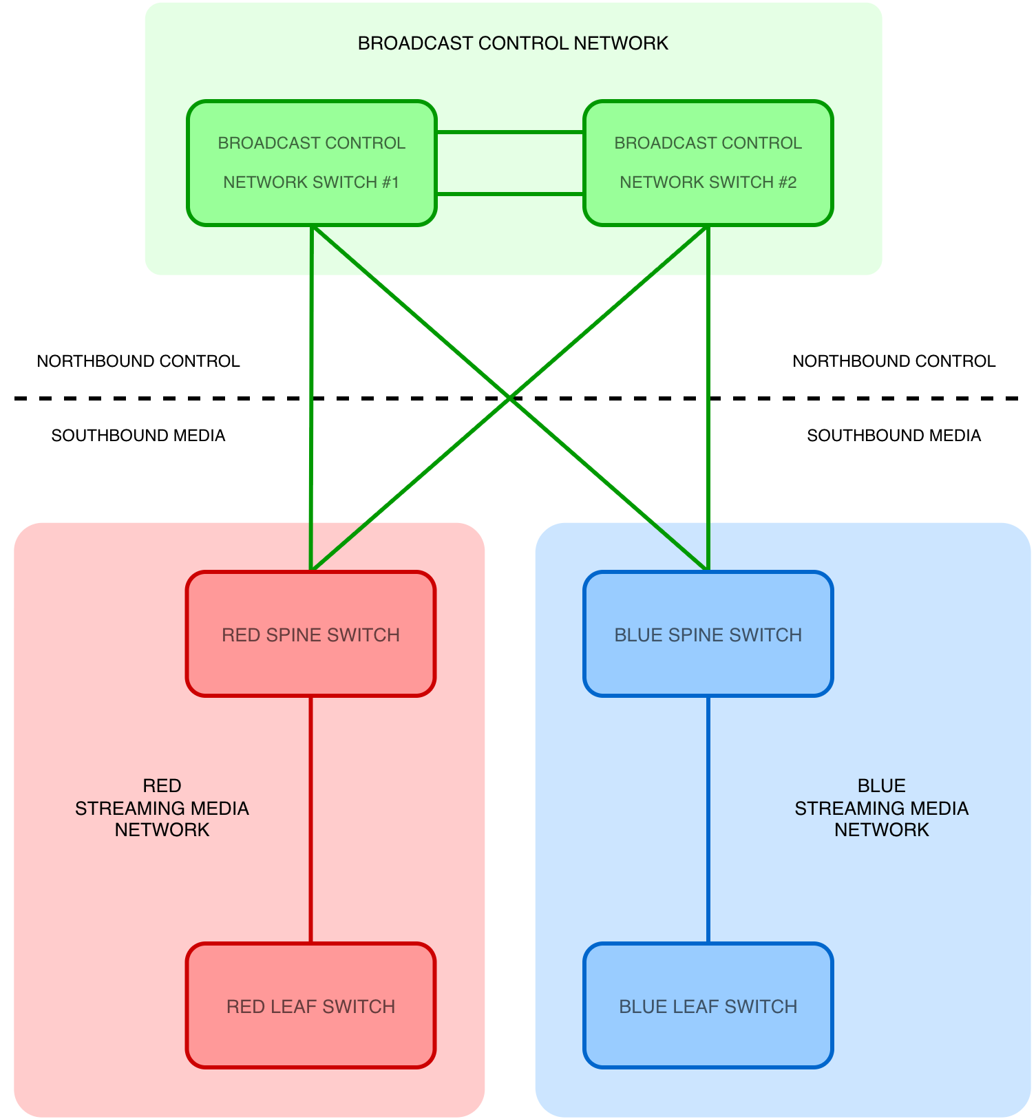
In an IP broadcast facility, the role of the Broadcast Control network is to:
- Facilitate the registration and configuration of broadcast control and media endpoints
- Manage and co-ordinate the multicast flows in the Streaming Media networks
It does not transport video, audio and ANC streams. Instead, it carries the control, management, monitoring and optional timing traffic (e.g. Network Time Protocol) that makes an IP broadcast facility work.
Functions
The Broadcast Control network provides the platform for an engineer or operator to:
- View device inventory
- Configure and manage endpoints
- Route signals
- View monitoring and telemetry information
- Configure security and authentication policies
Key Lawo Product Lines
Below is a description of Lawo products that operate in the Broadcast Control network:
HOME
HOME is a management platform for IP-based media infrastructures. It is designed to connect, manage and secure endpoints used in broadcast production environments. HOME provides the tools and centralised services for engineers to effectively interact with devices.

COTS Hardware Platforms
- Single HOME server
- HOME server cluster (three servers)
Modes of Operation
- Multi-homed (connected to multiple networks)
- Multiple IP addresses per server
- Out-of-band communication via media interfaces as well as control interfaces
- Single-homed or Dual-homed (connected to a single network - recommended)
- Single IP address per server
- In-band communication via control interfaces only, requires the network to route traffic from the Broadcast Control network to Streaming Media networks
- Necessary for registering and controlling devices that do not have dedicated control network interfaces, e.g. A__madi6, A__mic8, Edge One
VSM & Gadget Server
Virtual Studio Manager (VSM) is Lawo's advanced, IP-based broadcast controller and workflow platform. VSM provides a single, vendor-agnostic environment to control all production devices:
- Video and audio routers
- Vision switchers
- Audio consoles
- Multiviewers
- Intercoms
- etc.
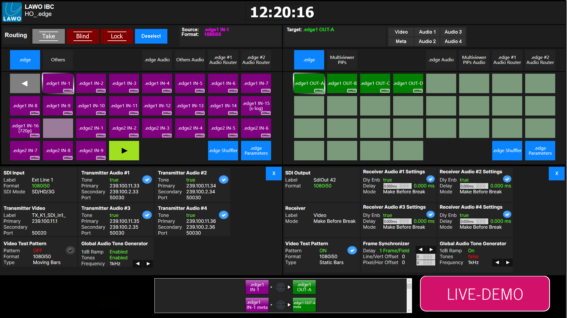
VSM allows engineers and operators to create custom broadcast workflows and user interfaces, tailored to specific needs, helping streamline complex tasks into intuitive actions. VSM is built around a modern TCP/IP backbone, supporting traditional baseband and all-IP broadcast infrastructures. A key component of the VSM platform is 'Gadget Server' (GS), a software product that acts as a communication and control protocol translator, enabling VSM to support and interact with third-party equipment, regardless of manufacturer.
COTS Hardware Platforms
- Single VSM server
- Single Gadget Server server
- VSM & Gadget Server server cluster (two to six servers)
- Hardware control panels
- Software control panels (on touchscreens)
Modes of Operation
- Single-homed or Dual-Homed (connected to a single network)
- Single IP address per server
- In-band communication via control interfaces only, requires the network to route traffic from Broadcast Control network to Streaming Media networks
Although both products interact with devices and apps, they perform different functions.
- HOME focuses on device management, registration, security and infrastructure orchestration
- VSM focuses on operational workflows, user interfaces and production control
In many deployments the two systems work together, with HOME managing the infrastructure and VSM providing the operational control layer.
Broadcast Control Network - Summary
- Facilitates the registration and configuration of broadcast control and media endpoints
- Manages and co-ordinates the multicast flows in the Streaming Media networks
HOME - Management and Orchestration Platform
- A software product
- Runs on COTS hardware
- Enables engineers to effectively connect and configure devices
- Performs basic signal routing
VSM & GS - Broadcast Controller
- Software products
- Run on COTS hardware
- Enable engineers and operators to design broadcast workflows
- Perform complex signal routing workflows
- Integrate and communicate with a wide range of third-party vendor equipment
NMOS (Networked Media Open Specification)
In IP-based broadcast systems, control and orchestration of media devices is commonly achieved using NMOS, developed by the Advanced Media Workflow Association (AMWA). NMOS defines a set of open standards that enable devices and control systems to:
- Discover each other on the network
- Exchange information about available resources
- Establish and manage media connections
NMOS does not transport media itself. It provides the mechanisms used to discover devices and establish media connections.
Within an SMPTE ST 2110 environment, NMOS provides a vendor-agnostic mechanism for interoperability between equipment from different manufacturers.
Key NMOS Specifications
- IS-04 – Discovery & Registration
- Devices register their presence and capabilities (e.g. senders and receivers) with an NMOS registry, a centralised service that maintains an inventory of all available resources on the network. Controllers query this registry to discover devices and their capabilities.
- IS-05 – Connection Management
- Controllers establish and manage connections between senders and receivers
In practical terms, the NMOS registry acts as a central directory of all available devices, senders, and receivers within the system. Once devices are registered via IS-04, controllers can use IS-05 to create and manage connections between them.
Lawo Control Architecture and NMOS Interoperability
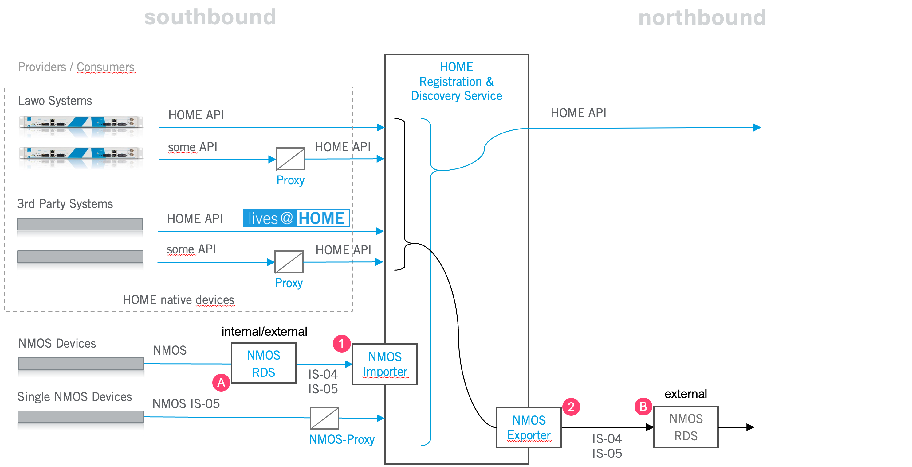
For HOME-native Lawo and third-party (Lives@HOME) products, device and control functionality is provided by HOME:
- Centralised device registration (with redundancy)
- Device configuration and management
- Connection control and orchestration
This is achieved via the HOME API (discussed further in a later chapter), which acts as the primary control interface within the system.
In NMOS-based workflows, IS-04 provides discovery and registration, while IS-05 provides connection management. In HOME-native workflows, similar functions are handled through HOME’s internal services and API. HOME can interoperate with NMOS systems, but HOME-native routing does not require NMOS to be the primary control mechanism. In NMOS-based systems, an NMOS registry is required to enable discovery and control. HOME fully supports interoperability with NMOS-based environments by enabling import and export of NMOS devices from and to an external IS-04 registry. In cases where no external IS-04 registry is present, HOME can provide an internal easy-nmos IS-04 registry.
- NMOS Importer
- Allows devices registered in an external NMOS registry to be imported into HOME
- Can be internal or external to HOME
- NMOS Exporter
- A separate license for HOME
- Exports a list of devices registered in HOME to an external NMOS registry
This approach enables Lawo systems to:
- Operate using an optimised internal control architecture
- Maintain compatibility with third-party NMOS-based systems
Stream Patching
In an IP broadcast network, routing or 'patching' a signal from a sender to a receiver is not a physical, electrical crosspoint like in an SDI baseband router. It is a 'control' action in the Broadcast Control network that results in a subscription to a multicast stream in the Streaming Media networks.
Separate Functions
In SMPTE ST 2110 systems, there are two fundamental network functions to consider: control and media.
Control (Broadcast Control network)
- Broadcast Controllers and Orchestrators
- e.g. VSM and HOME
- NMOS IS-04 (registration)
- NMOS IS-05 (connection management)
Media (Streaming Media networks)
- Multicast RTP flows (video, audio, ANC)
- IGMP joins/leaves
- PIM (Protocol Independent Multicast, used to route multicast traffic between network segments — described in the 'Key Network Concepts' section)
The Broadcast Control system, via the Broadcast Control network, tells devices which multicast groups to subscribe to — the Streaming Media network then forwards the video, audio and ANC packets
Session Description Protocol (SDP)
Session Description Protocol (SDP) is used to describe the characteristics of ST 2110 media streams, providing the information receivers require to establish connections and interpret incoming media. SDP information may be generated by the sending device or provided through a control or orchestration system, depending on the implementation. It can be exchanged as a file or communicated through an API, without requiring a physical SDP file to be transferred between devices. The SDP contains:
- Source IP addresses (unicast) of the media streams (RED and BLUE, where applicable)
- Multicast IP addresses of streams (for RED and BLUE networks)
- UDP port number (Port #)
- Payload type
- Format parameters
Excerpt from an audio SDP file
| SDP Row | Description |
|---|---|
v=0 | SDP Version |
o=- 0 1 IN IP4 172.20.0.58 | Sender IP address |
a=group:DUP primary secondary | RED and BLUE streams (ST 2022-7) |
m=audio 9000 RTP/AVP 97 | Start of RED stream description |
c=IN IP4 239.100.1.1/255 | IPv4 multicast address/packet TTL |
a=source-filter:incl IN IP4 | IPv4 multicast address/sender IP address |
a=rtpmap:97 L24/48000/8 | RTP payload = 97/audio codec = L24/sample rate = 48kHz/channel count = 8 |
a=ts-refclk:ptp=Ieee1588-2008:00-02-c5-ff-fe-19-38-0a:0 | MAC address of PTP Grandmaster Clock |
a=ptime:1 | Packet time of 1ms |
a=mid:primary | End of RED stream description |
m=audio 9000 RTP/AVP 97 | Start of BLUE stream description |
c=IN IP4 239.101.1.1/255 | IPv4 multicast address/packet TTL |
a=source-filter:incl IN IP4 | IPv4 multicast address/sender IP address |
a=rtpmap:97 L24/48000/8 | RTP payload = 97/audio codec = L24/sample rate = 48kHz/channel count = 8 |
a=ts-refclk:ptp=Ieee1588-2008:00-02-c5-ff-fe-19-38-0a:0 | MAC address of PTP Grandmaster Clock |
a=ptime:1 | Packet time of 1ms |
a=mid:secondary | End of BLUE stream description |
Example Signal
As an example, assume:
- A camera connected to a .edge gateway transmitting 2110-20 video (sender)
- A monitor connected to a .edge gateway receiving 2110-20 video (receiver)
- Multicast: 239.1.1.1:5004
To patch a signal, VSM or HOME can obtain the SDP information by making an API call to a sender. VSM or HOME then sends the SDP information to the receiver, again via an API call.
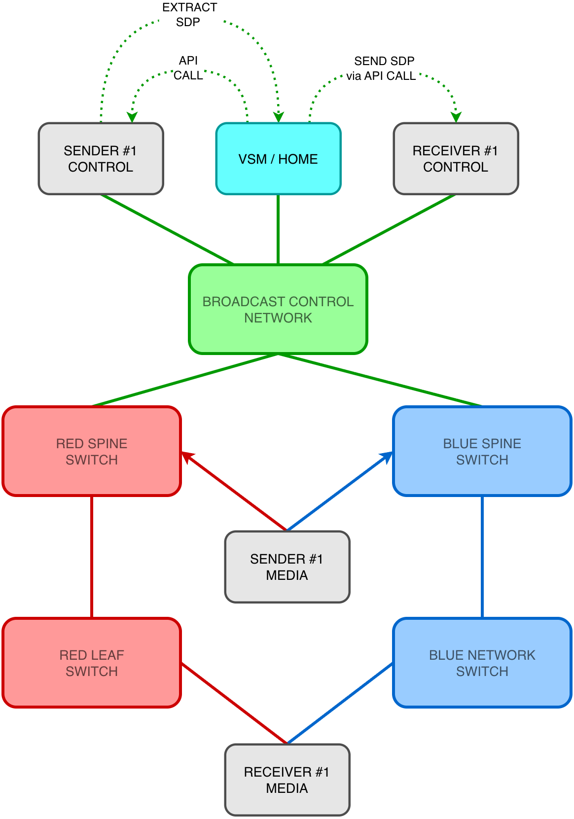
The receiver reads the SDP and extracts:
- Multicast group: 239.1.1.1
- Port: 5004
- Unicast source address of sender
The receiver sends an IGMP Membership Report (‘join’) message to its local network switch, indicating its interest in receiving the multicast stream. The switch processes this membership information and updates the relevant multicast forwarding state. If the stream is already available, forwarding can begin immediately. Otherwise, additional multicast routing operations may be required to establish a path towards the sender.
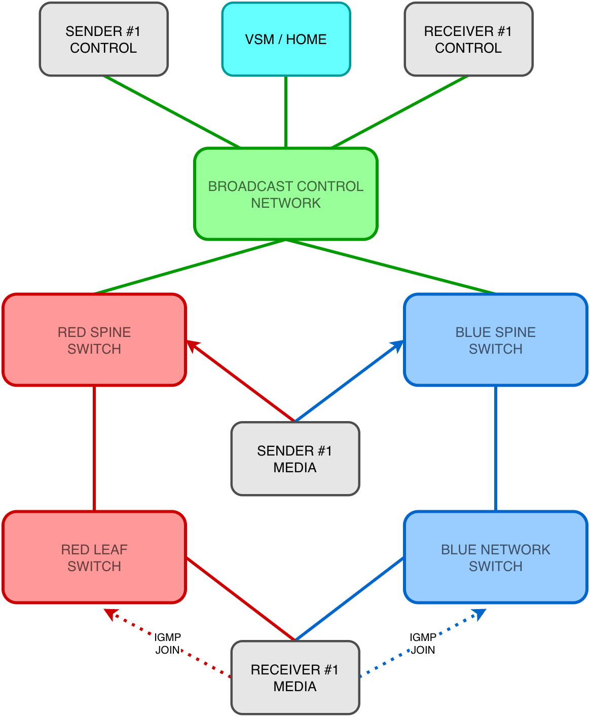
If the multicast source is located in another subnet and multicast routing is required:
- The receiver’s local multicast router (known as the last-hop router) processes the IGMP membership information
- The last-hop router uses PIM to establish the required multicast forwarding state towards the source or Rendezvous Point (RP), depending on the multicast routing mode
- PIM Join messages propagate upstream through the routed network, establishing the multicast distribution tree
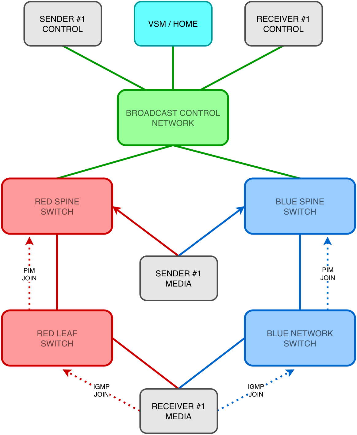
The RTP flow starts arriving:
- RTP packets flow from sender to receiver
- The Streaming Media switches forward the multicast data only to the subscribed ports
- The receiver locks to the stream
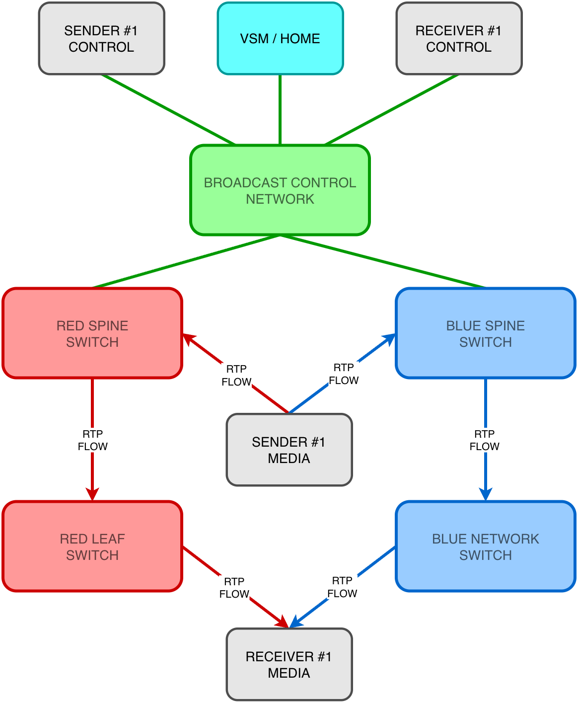
The signal is 'patched'.
It is possible for broadcast control systems to read an SDP from a sender and write it to a receiver using different protocols — e.g.
- HOME API (NATS)
- EmBER+
- NMOS (HTTP/JSON)
Different broadcast controllers implement this process in different ways, but from a network perspective they are all treated the same.
From an operator perspective, this entire process is abstracted into a simple routing action, while the system performs the required control and network operations automatically. In a traditional SDI router, a route is created by changing a physical crosspoint. In an ST 2110 system, a route is created by changing multicast subscriptions.
Stream Patching - Summary
- SDPs describe multicast streams and are a key component of an ST 2110 system
- HOME and VSM use SDPs and abstractions of SDPs (SorDs and Signal Paths) to perform stream patching
- HOME API, EmBER+ and NMOS are protocols used for stream patching
Key Network Concepts
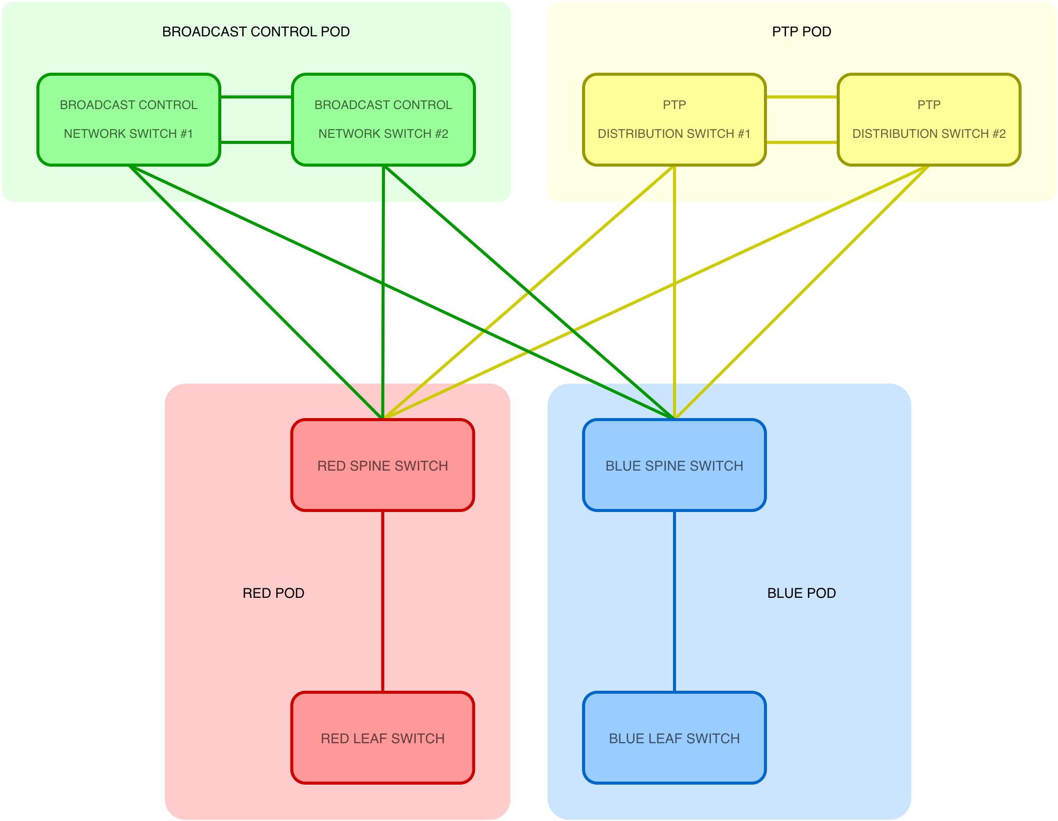
In IP broadcast facilities, the Broadcast Control, Streaming Media and optional dedicated PTP networks are designed as logically or physically separate instances of Spine-Leaf networks. These Spine-Leaf instances are sometimes referred to as fabrics or network 'points of delivery' (POD). The switches that make up the network PODs require a way to automatically learn how to reach each other. Therefore, these network PODs are unified through the use of dynamic routing protocols and multicast routing mechanisms. A routed architecture provides scalability, resilience and predictable behaviour across a facility.
The previous section described how streams are patched; this section explains how the network enables those streams to be delivered.
In-band and Out-of-Band Communication
In an IP broadcast facility, control systems and broadcast controllers can communicate with devices in two different ways: out-of-band and in-band.
Out-of-Band (OOB) Communication
Out-of-band communication occurs over dedicated Control network interfaces. In this model:
- The broadcast controller connects to a device via its control network interface(s)
- Configuration, monitoring and connection management are performed separately from the media streams
- The Streaming Media networks (RED and BLUE) remain dedicated to transporting RTP media flows
This approach provides:
- Clear separation between control and media
- Improved security and fault isolation
- Easier troubleshooting
OOB control is common in larger facilities where control and media networks are intentionally separated for operational stability.
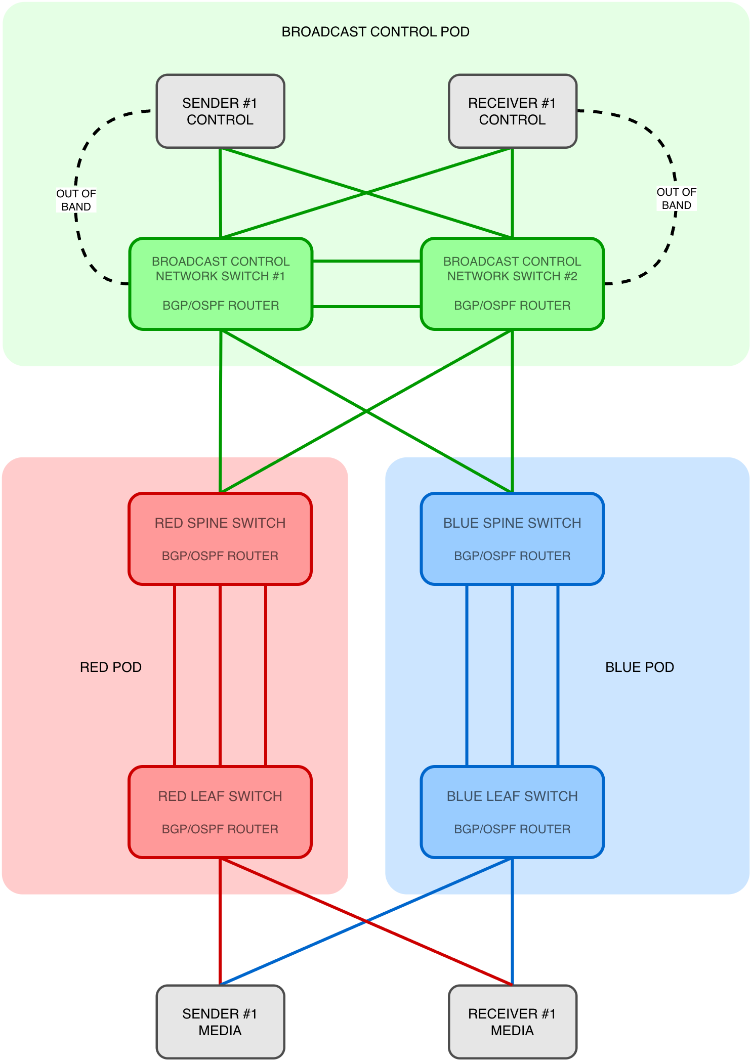
In-band Communication
In-band communication occurs when control traffic shares the same physical interface as the Streaming Media network. In this model:
- The broadcast controller communicates with devices through their Streaming Media interfaces
- Control protocols traverse the same routed network as media traffic
- No separate control cabling is required
This can simplify deployment and reduce infrastructure requirements (e.g. cabling), particularly in smaller or distributed systems. Both approaches are valid; the choice can depend on the scale of the facility, operational requirements, device limitations or economic reasons. Understanding how these categories of network interfaces interact and how protocols coordinate communication between devices is essential when designing or deploying an IP facility.
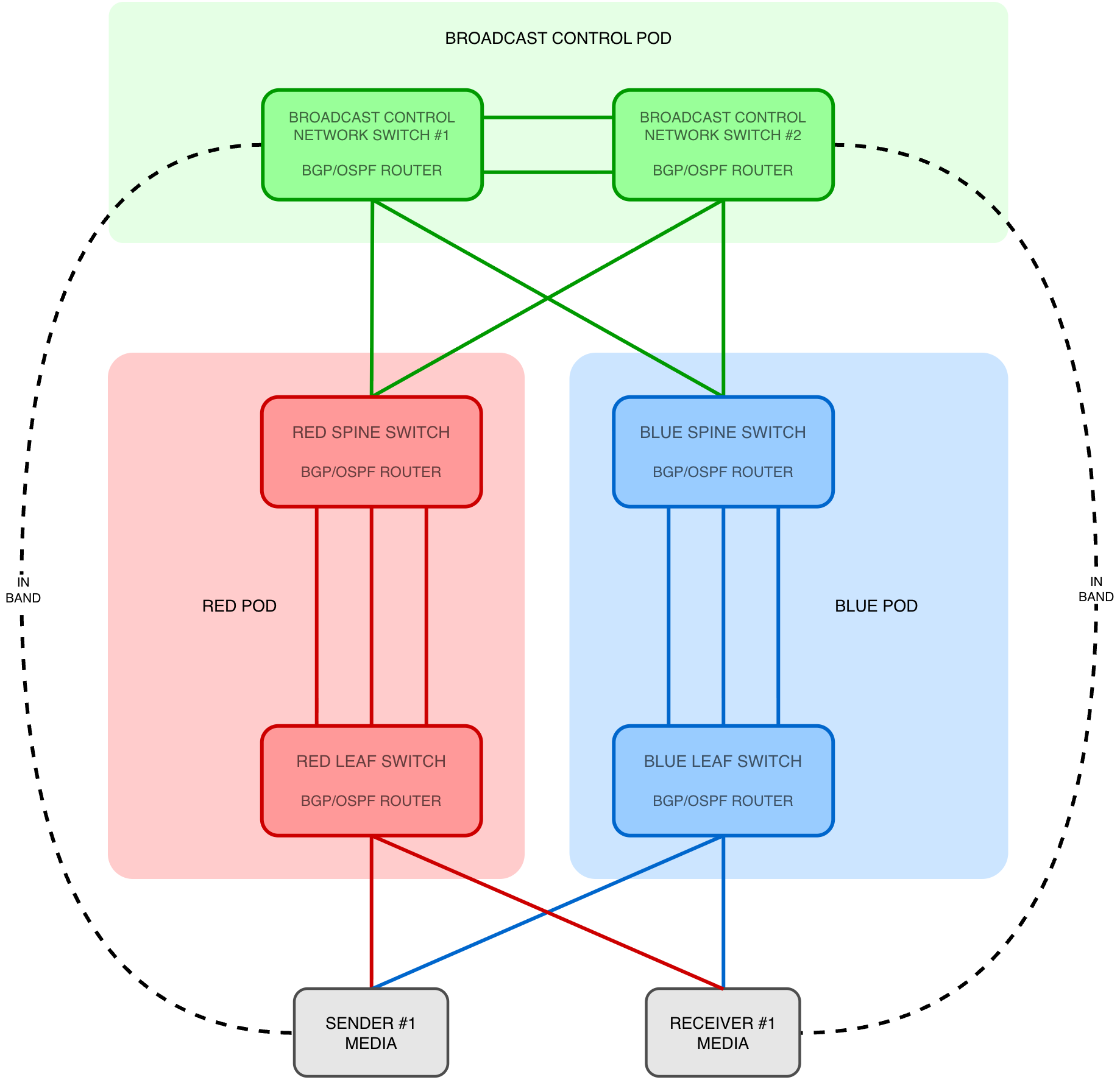
By implementing dynamic routing:
- In-band (via an endpoint's media network interfaces) traffic can traverse routed interfaces properly
- Control network interfaces (OOB)
- PTP distribution can operate across L3 boundaries when properly designed
Dynamic routing allows network devices to detect topology changes and automatically calculate alternative paths when available. This reduces the need for manual intervention following a network failure and helps maintain connectivity between network PODs. However, recovery depends on the availability of alternative paths and the convergence behaviour of the routing protocol.
Dynamic Unicast Routing Protocols
Dynamic routing protocols such as Border Gateway Protocol (BGP) and Open Shortest Path First (OSPF) allow the network to:
- Automatically learn about available paths to other network PODs
- Detect failures
- Re-route traffic without manual intervention
- Keep all parts of the system reachable
- Provide the network-control foundation that ties all the network PODs together
- Enable resilient in-band communication between network PODs
- e.g. - HOME/VSM to media devices via their streaming media interfaces
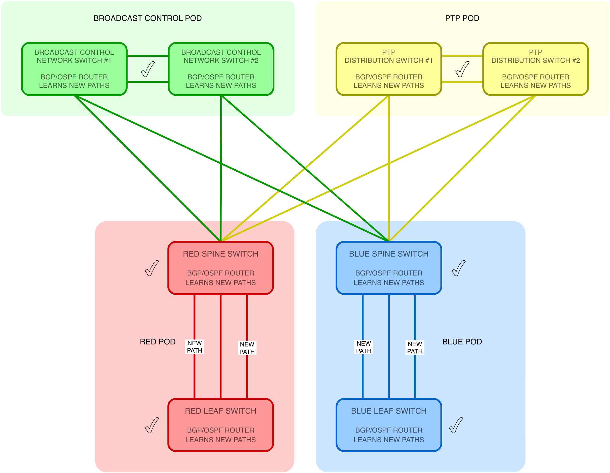
There are two common routing protocols used in IP broadcast facilities: BGP and OSPF.
OSPF
OSPF is commonly used to allow switches within a facility to automatically share information about:
- Which networks (IP ranges) they are connected to
- Which paths (physical links) are available
- Which paths are preferred
If a cable or switch fails:
- OSPF detects the failure
- The network recalculates the best available path
- Traffic is automatically redirected
This process can happen in seconds (or faster) and without manual configuration changes. For broadcast engineers, OSPF can be thought of as:
Dynamic routing helps maintain connectivity for control and media traffic following network failures, provided alternative paths are available. However, the time required to detect a failure and establish a new route depends on the routing protocol, network topology and configuration. For real-time media applications, additional redundancy mechanisms such as ST 2022-7 may be required to maintain uninterrupted service during network convergence.
BGP
BGP is capable of what OSPF achieves, but it is often used in larger or more complex facilities where PODs are required to:
- Scale to large numbers of devices
- Apply strict routing policies (control which PODs can talk with each other)
- Keep different domains organised and structured
- Manage multiple IP facilities that are required to connect to each other
In simpler terms:
BGP improves scalability and predictable traffic engineering in larger deployments, particularly where multiple network PODs or security domains must interconnect and be carefully maintained.
Without dynamic routing:
- Every path would need to be manually configured (static routing)
- Failures would require manual intervention
- Scaling the system would be slow and error prone
With dynamic routing:
- The holistic network topology becomes self-updating
- Failures are handled automatically
- New network PODs can be added with minimal disruption (e.g. additional media processing networks such as NDI or other IP domains)
- Lays the foundation for multicast routing mechanisms (PIM)
For engineers new to IP, the key takeaway is:
Dynamic routing allows the network to behave like a resilient baseband router — automatically maintaining signal paths where possible, even when hardware fails.
Switch Uplinks using /30 and /31 Interfaces
In routed Spine-Leaf or POD interconnect designs, point-to-point routed uplinks are commonly addressed using /30 or /31 subnets. These subnet sizes are ideal for point-to-point links because:
- Only two useable addresses are required
- They minimise wasting IP address space
- They clearly define link boundaries
- They reduce broadcast domains
- They eliminate reliance on large shared VLANs
| Feature | /30 Network | /31 Network (point-to-point) |
|---|---|---|
| Subnet Mask | 255.255.255.252 | 255.255.255.254 |
| Total IP Addresses | 4 | 2 |
| Usable Host Addresses | 2 | 2 |
| Network Address | Yes | No |
| Broadcast Address | Yes | No |
| Use Case | Small LANs, point-to-point links | Point-to-point links only |
| Efficiency | Lower | Higher |
| Example Subnet | 192.168.1.0/30 | 192.168.1.0/31 |
| Example usable IPs | .1 and .2 | .0 and .1 |
Benefits in Broadcast IP Networks
Using routed point-to-point links provides:
- Failure domain isolation (no L2 flooding between network PODs)
- Predictable convergence behaviour
- Reduced multicast ambiguity
- Improved troubleshooting clarity
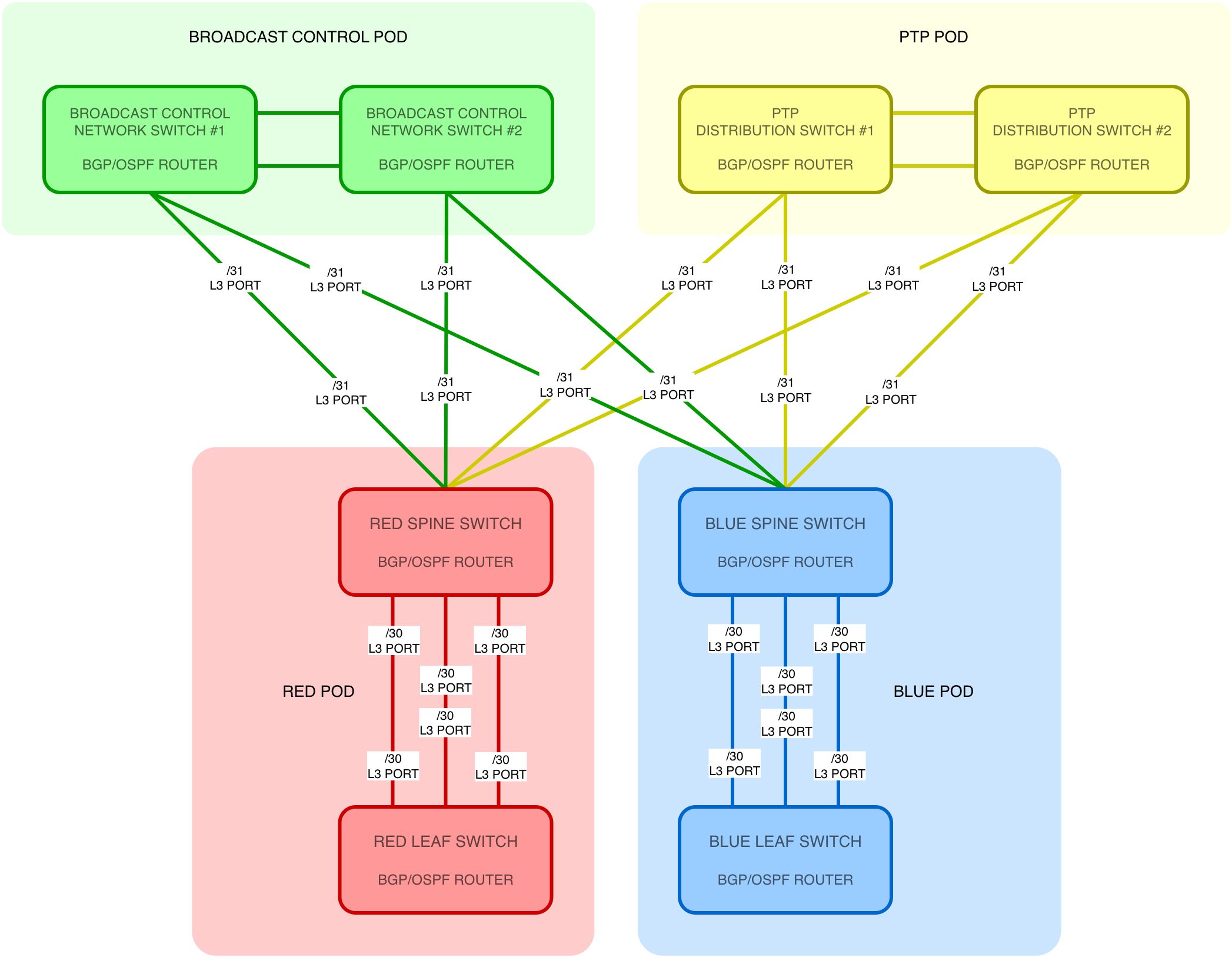
/31 addressing (RFC 3021) is particularly efficient for Spine-Leaf links because it supports exactly two endpoints with no broadcast address requirement. This design replaces large Layer 2 trunks with clear Layer 3 boundaries, improving scalability and operational stability.
Leaf-Switch Mobility
- Dynamic routing can also support the relocation of leaf switches within a facility without requiring changes to the IP addressing of connected media devices
- By using IP unnumbered interfaces or dynamically assigned point-to-point addressing, a leaf switch can establish new routed uplinks when connected to a different part of the network. Provided the necessary routing configuration and network services are available, the leaf switch can advertise its existing endpoint subnets through the new uplinks
- This allows the connected devices to retain their IP addresses while the network automatically learns their new location
Multicast Routing Mechanisms
ST 2110 media transport relies heavily on multicast (video, audio and ANC). PTP may also use multicast depending on system design. A routed architecture requires a multicast routing protocol to move streams between switches and devices that do not share the same IP address range, subnet or VLAN.
Internet Group Management Protocol (IGMP)
IGMP operates between multicast receivers and their local multicast router (known as the last-hop router), which is often integrated into a network switch. It:
- Allows devices to join or leave multicast groups
- Signals interest in specific RTP streams
- Enables multicast forwarding states to be created at the first-hop router
IGMP itself does not route multicast; it simply informs the network which stream is required.
Protocol Independent Multicast (PIM)
PIM does not carry multicast traffic itself; it builds the forwarding state that allows multicast traffic to follow paths determined by the unicast routing table. PIM relies on unicast routing protocols (e.g. BGP, OSPF) to determine the best path(s) through the network and enables multicast routing across L3 boundaries. It:
- Builds multicast distribution trees across the routed network
- Establishes multicast forwarding state so that network devices can replicate and forward streams towards network segments with interested receivers
- Scales efficiently in sparse multicast environments (sparse-mode) — typical in broadcast
PIM Sparse-Mode (PIM-SM) is commonly used in ST 2110 facilities because:
- Not all devices subscribe to all streams (a sparse subscription model)
- Multicast groups are joined selectively
- It avoids unnecessary flooding like in L2 multicast environments
IGMP and PIM-SM allow multicast streams to traverse network pods cleanly and efficiently while preserving bandwidth and predictable routing behaviour. Together, these concepts form the foundation of a modern IP broadcast infrastructure, where control, timing, and media transport operate as coordinated but independent systems.
Key Network Concepts - Summary
- Dynamic routing protocols (e.g. BGP, OSPF) enable network PODs to exchange routing information and communicate reliably
- Dynamic routing supports both in-band (media interfaces) and out-of-band (control interfaces) communication
- /30 and /31 routed uplinks create efficient Layer 3 boundaries, improving scalability and stability
- Routed architectures reduce Layer 2 complexity and improve fault isolation
- IGMP signals multicast membership at the network edge (receivers to switches)
- PIM-SM enables multicast streams to be routed across Layer 3 networks
- PTP can traverse the same routed infrastructure when properly designed
- The overall architecture allows multiple network PODs to operate as a unified, resilient broadcast fabric
The next chapter explains the relationship between HOME and VSM, and the key communication protocols they use for registering and controlling devices.