2. Streaming Media Networks and PTP Integration/Distribution
Streaming Media Networks
The role of the Streaming Media networks is to transport real-time media traffic throughout an IP broadcast operation, which may consist of distributed hubs. Video, audio and ancillary (ANC) data are carried across the network as IP media streams, allowing sources and destinations to communicate without dedicated point-to-point cabling. Media streams may be generated natively by ST 2110-capable devices or created by gateways and stageboxes that convert traditional baseband signals into IP. Once on the network, these media streams are transported using RTP and are typically distributed using multicast.
This architecture enables:
- Low-latency transport of media signals using Ethernet switching
- Accurate timing and synchronisation using PTP
- Efficient one-to-many signal distribution using multicast
- Seamless Protection Switching (SPS) using ST 2022-7
Streaming Media networks can also transport additional media formats and services, including:
- ST 2110-22 compressed video streams such as JPEG XS
- Proxy video streams used by applications such as HOME Multiviewer
- AES67/RAVENNA audio streams
- Metadata and ancillary data services
A well-designed Streaming Media network can provide routing behaviour similar to a non-blocking SDI router, but implemented using Ethernet switching technology. Unlike baseband infrastructures, where each signal requires a dedicated cable and physical router port, an IP network can transport many independent media streams across a shared high-bandwidth infrastructure. This approach can significantly reduce cabling volume, physical I/O requirements and reference distribution infrastructure while providing greater flexibility for routing, processing and future expansion. By increasing network bandwidth or adding switching capacity, systems can scale more easily to accommodate changing operational requirements.
Functions
Essence Transport (RTP Multicast)
ST 2110 separates media into independent flows or 'essences':
| Standard | Transports |
|---|---|
| ST 2110-10 | System Timing & Definitions |
| ST 2110-20 | Uncompressed Video |
| ST 2110-21 | Traffic Shaping and Delivery Timing for Video |
| ST 2110-22 | Constant bit-rate compressed video (e.g. JPEG XS) |
| ST 2110-30 | PCM Audio |
| ST 2110-31 | AES3 Transparent Audio Transport |
| ST 2110-40 | ANC Data |
| ST 2110-41 | Fast Metadata Framework |
| ST 2110-43 | Timed Text Markup Language for Captions and Subtitles |
Each essence is:
- RTP-encapsulated
- Multicast traffic
- Assigned RTP sequence numbers and timestamps, while relying on PTP as a shared time reference so receivers can accurately align related video, audio and ANC essences
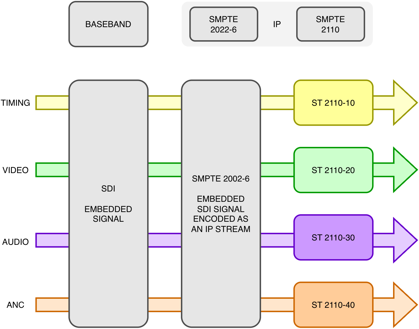
Unlike SDI, where video, audio, and ancillary data are typically embedded into a single signal, SMPTE ST 2110 defines the transport of these essences as separate synchronised streams over IP networks. This architecture enables benefits such as independent routing of essences, flexible processing workflows, bandwidth optimisation based on subscription patterns, and interoperability between systems. Key benefits of this approach are:
- Independent routing of essences
- Bandwidth efficiency (based on subscription patterns)
- Clean interoperability
- Processing flexibility (e.g. HOME Apps)
- Alignment at the receiver
High-Bandwidth Signal Distribution
A Streaming Media network for video applications must support high-bandwidth switch interfaces:
- 10/25/40/50/100/400Gbps links (Gbps= gigabits per second)
Line-rate forwarding describes a switch’s ability to process and forward traffic at the full supported speed of its interfaces. A non-blocking switching architecture allows traffic to be forwarded without internal bandwidth limitations under supported operating conditions. However, packet loss can still occur when multiple traffic flows exceed the available bandwidth of an outgoing interface, or when temporary traffic bursts exceed the switch’s buffering capacity. Consequently, careful bandwidth planning, traffic management and appropriate network design remain essential for reliable, uninterrupted media transport.
- Low latency
| Standard | Type | Frame Rate | ST 2022-6 Gbit/s | ST 2110-20 Gbit/s |
|---|---|---|---|---|
| SMPTE 2036 | UHD-3840 | 60p | 11.88 | 9.95 |
| SMPTE 2036 | UHD-3840 | 59.94p | 11.88 | 9.94 |
| SMPTE 2036 | UHD-3840 | 50p | 11.88 | 8.29 |
| SMPTE 424M | HD-1080 | 60p | 2.97 | 2.49 |
| SMPTE 424M | HD-1080 | 59.94p | 2.97 | 2.49 |
| SMPTE 424M | HD-1080 | 50p | 2.97 | 2.07 |
| SMPTE 424M | HD-1080 | 60i | 1.49 | 1.25 |
| SMPTE 424M | HD-1080 | 59.94i | 1.49 | 1.25 |
| SMPTE 424M | HD-1080 | 50i | 1.49 | 1.04 |
| SMPTE 296M | HD-720 | 60p | 1.49 | 1.11 |
| SMPTE 296M | HD-720 | 59.94p | 1.49 | 1.10 |
| SMPTE 296M | HD-720 | 50p | 1.49 | 0.92 |
The bandwidth figures represent the nominal active-picture video payload for uncompressed 10-bit, 4:2:2 signals. They exclude RTP, UDP, IP and Ethernet overhead. Actual network bandwidth requirements will therefore be slightly higher and depend on packetisation and the sender’s traffic-shaping behaviour.
A Streaming Media network for audio applications should also support some high-bandwidth switch interfaces, particularly interfaces that uplink to other switches:
- 1/10/25Gbps links
- Line-rate forwarding
- Low latency
| Standard | Type | Sample Rate | Channels | Packet Time | Mbit/s |
|---|---|---|---|---|---|
| AES67 | L24 | 48kHz | 2 | 1ms | 2.96 |
| AES67 | L24 | 48kHz | 8 | 1ms | 10.04 |
| AES67 | L24 | 48kHz | 16 | 1ms | 19.48 |
| AES67 | L24 | 48kHz | 64 | 1ms | 76.12 |
| AES67 | L24 | 48kHz | 128 | 1ms | 151.64 |
| AES67 | L24 | 96kHz | 64 | 1ms | 151.64 |
| AES67 | L24 | 48kHz | 64 | 125µs | 92.51 |
| AES67 | L24 | 96kHz | 64 | 125µs | 167.02 |
Streaming Media networks for both video and audio applications can also use 'Multi-Gigabit' (mGig) interfaces where applicable. mGig interfaces are RJ45 ports which operate over standard copper cabling in order to provide higher bandwidth without requiring fibre or new cabling. An mGig interface can operate at several Ethernet speeds, typically:
- 100Mbps
- 1Gbps
- 2.5Gbps
- 5Gbps
- 10Gbps (on some devices)
Lawo recommends testing switches with mGig interfaces ahead of deployment to confirm PTP performance and stability.
Multicast Traffic Management
Multicast is the primary communication method used in Streaming Media networks. It allows a single device to transmit data to several other devices in an efficient and scalable way. At a very high level, network switches and routers can perform three functions:
- Learn about a network
- Forward traffic to relevant devices on a network
- Flood traffic to an entire network
On unmanaged, poorly configured and un-configured networks, multicast will be flooded to all ports and devices on the same network segment (subnet/VLAN). In order to mitigate this, protocols can be configured on network switches to control the flow of multicast:
IGMP (Internet Group Management Protocol)
A Layer 3 (Network layer) protocol
- A host-to-router signalling protocol used by receivers to indicate interest in multicast groups
- Enables devices to 'join' or 'leave' multicast streams
- In routed networks, multicast routers use IGMP information together with multicast routing protocols such as PIM (explained in a later chapter) to determine where multicast traffic should be forwarded
- Operates between switches configured as multicast routers and end devices
- Tells routers which devices want multicast traffic
IGMP Snooping
- A Layer 2 (Data Link Layer) feature of the IGMP protocol
- Switches 'snoop' (listen to) IGMP messages to learn which ports need specific multicast traffic
- Prevents multicast traffic from being flooded to all ports and devices in a subnet/VLAN
- Requires an IGMP Querier (broker) in each subnet/VLAN, typically configured on the switch
Using multicast in a controlled manner allows for:
- One sender to transmit to many receivers
- A signal routing behaviour that does not duplicate the bandwidth of the source (from a baseband perspective, this is analogous to removing the requirement for DAs)
- Multicast replication (analogous to distribution amplifiers)
- Efficient bandwidth utilisation
This is fundamental to replacing baseband routers.
Lawo encourages the use of Layer 3 routed Streaming Media networks (IGMP). Using Layer 2 switched Streaming Media networks (IGMP Snooping) should only be considered for Layer 2 'converged' networks:
- A converged network is a single, unified network infrastructure that carries multiple types of traffic instead of using separate dedicated networks for each application, e.g.
- Broadcast Control, RED and/or BLUE Streaming Media networks on one switch
| Feature | IGMP Snooping | IGMP / PIM |
|---|---|---|
| Scope | Layer 2 VLANs | Layer 3 Routed Interfaces |
| Complexity | Low | Medium-High |
| Scalability | Limited | High |
| Configuration | Easy | Requires unicast routing |
| Application | Small, simple facilities | Small, medium and large facilities |
Redundancy: ST 2022-7 Seamless Protection Switching
An important function and advantage of adopting Streaming Media networks is redundancy. The SMPTE ST 2022-7 standard defines 'seamless protection switching' (also called 'hitless merge').
Each sender device (TX) transmits:
- Two identical RTP streams
- Each stream is connected to different logical and/or physical networks
- Typically, these networks are called RED and BLUE
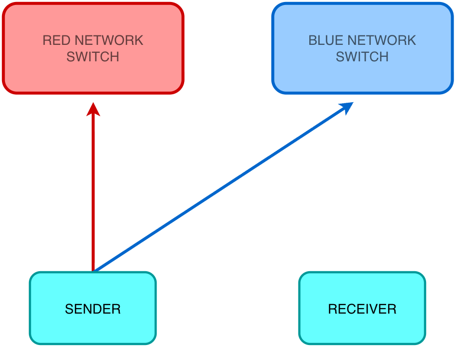
The receiver device (RX):
- Buffers both streams
- Constructs a single output stream based on the next expected RTP sequence numbers that can be derived from either RED or BLUE networks paths
- RTP packets with duplicate sequence numbers are ignored without disruption
- If an RTP packet with the expected sequence number arrives on time, in at least one of the networks, the stream can be reconstructed without disruption

When correctly engineered, if one path fails:
- No visible video disturbance
- No audible audio interruption
- No loss of service during a single network-path failure
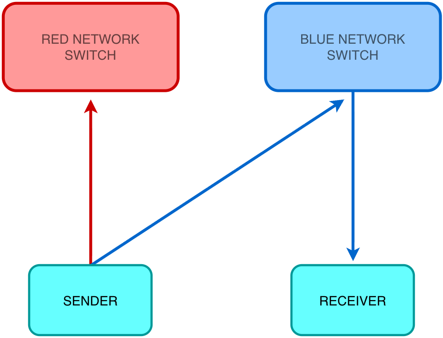
ST 2022-7 Architecture
The two networks are typically:
- Physically isolated from each other
- Logically independent
This provides:
- Stream/path redundancy
- Hardware fault tolerance
- Ability to upgrade network hardware without interrupting broadcast operations
It achieves High-Availability (HA) resilience inside an IP broadcast facility. It is also possible to combine the RED and BLUE networks on a single physical infrastructure ('converged' network), however care should be taken to mitigate potentially reduced hardware redundancy and the inability to perform upgrades without interrupting broadcast operations.
Key Lawo Product Lines
| Video Gateway | AV Stagebox | Audio Gateways | Audio Stageboxes | Audio Processing | AV Processing |
|---|---|---|---|---|---|
| .edge | Edge One | Power Core | A__line | A__UHD Core | HOME Apps |
| Power Core (RP) |
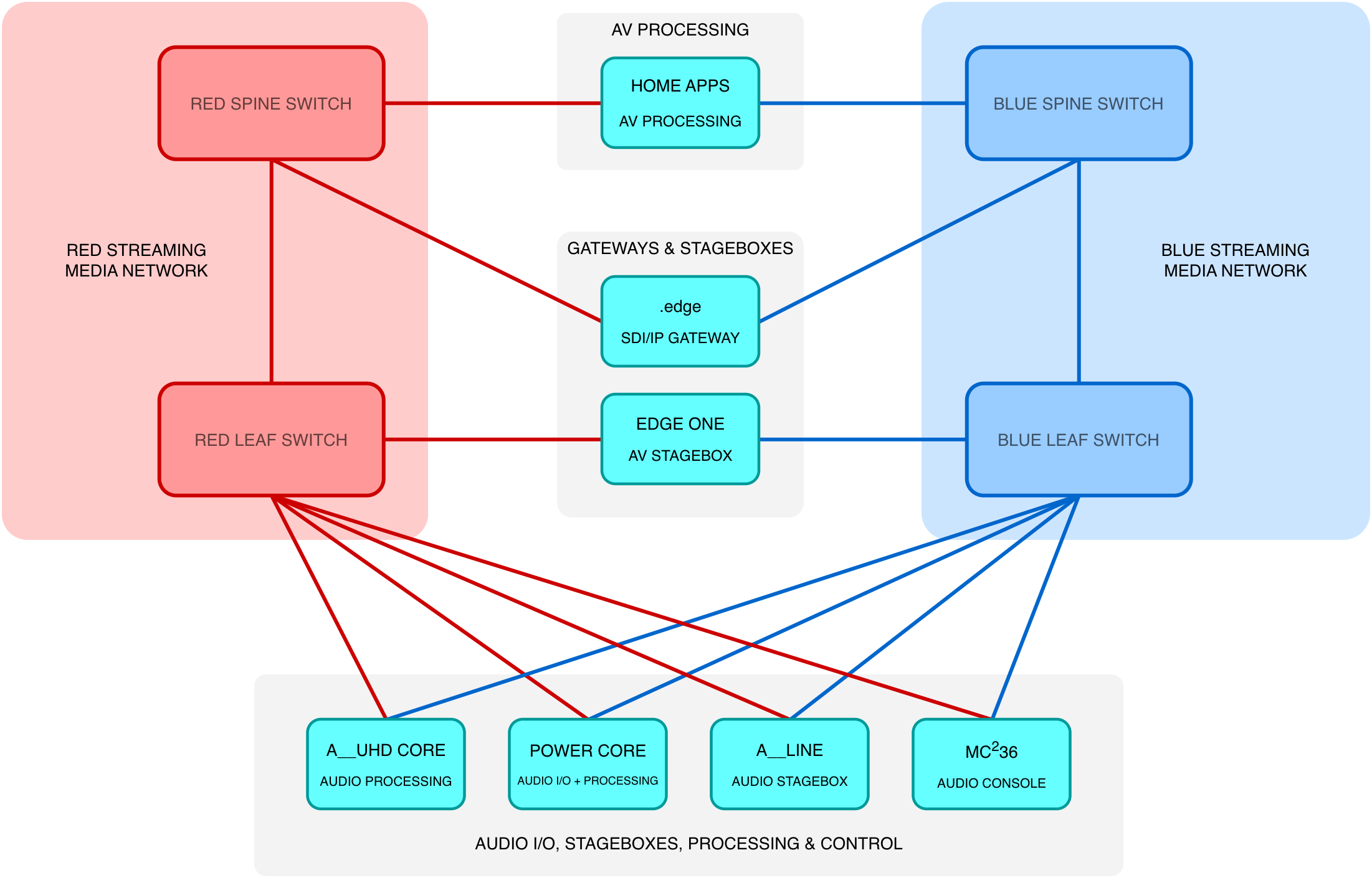
Streaming Media Networks — Summary
- Transport video, audio and ANC data traffic
- ST 2110 essences are encapsulated as RTP multicast flows
- Multicast streams carry RTP sequence numbers and timestamps
- Typically use high-bandwidth interfaces for signal distribution
- Control the flow of multicast traffic and manage devices joining and leaving multicast groups via IGMP/IGMP Snooping
- ST 2022-7 provides stream and network path redundancy (SPS)
- Rely on PTP as the shared time reference so receivers can align essences
In the next section, the role and function of PTP Integration and an optional dedicated distribution network will be explained.
PTP Integration & Distribution
Precision Time Protocol (PTP) is a crucial part of any IP broadcast facility. It performs the role traditionally provided by Black Burst or Tri-Level Sync, but distributes time across the network rather than distributing a physical reference signal. In an ST 2110 environment, video, audio and ANC are transported as separate RTP streams rather than embedded into a single signal. PTP provides the common timing reference that allows receiving devices to buffer, align and reconstruct these independent essences correctly. PTP messages are typically transported as multicast, allowing all relevant devices on the network to receive and synchronise to the same timing reference.
In simple terms, PTP ensures that every device in the system agrees on exactly what time it is, to within fractions of a microsecond.
- PTP over unicast transport is also possible, where timing messages are exchanged directly between specific devices rather than distributed to the network as a whole
PTP Integration Options
There are typically three approaches to integrate PTP grandmaster clocks (GMCs) into an IP broadcast facility;
- Via the Broadcast Control network, to the Streaming Media networks:
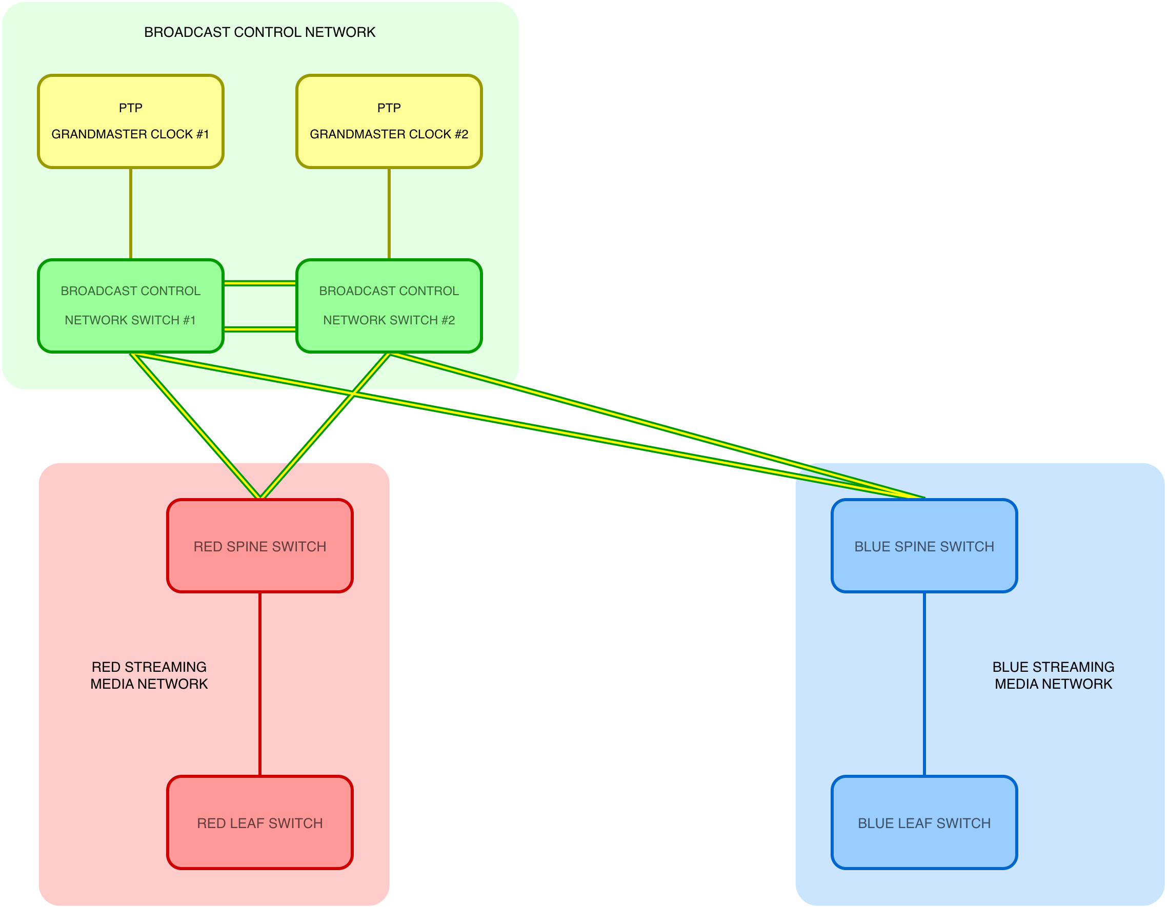
- Directly to the Streaming Media networks:
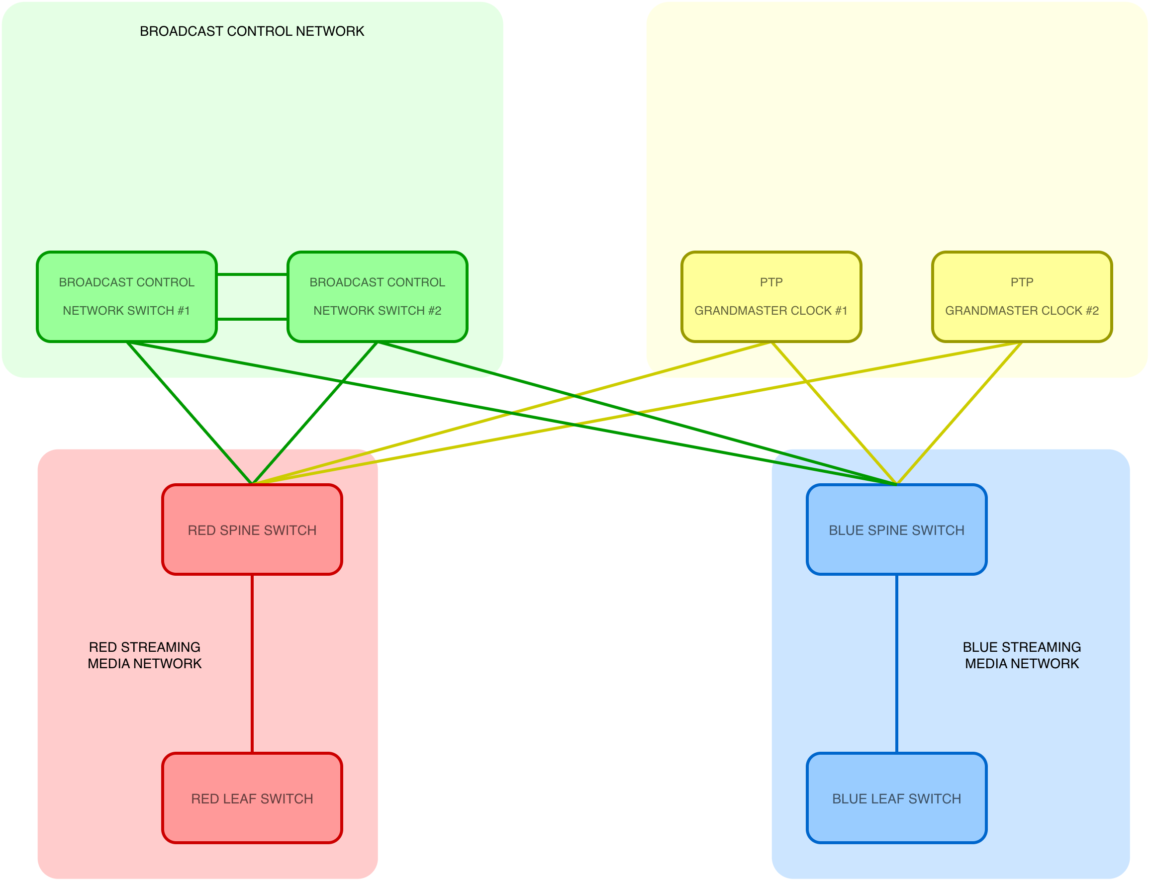
- Via dedicated network switches acting as a PTP Distribution network to the Streaming Media networks:
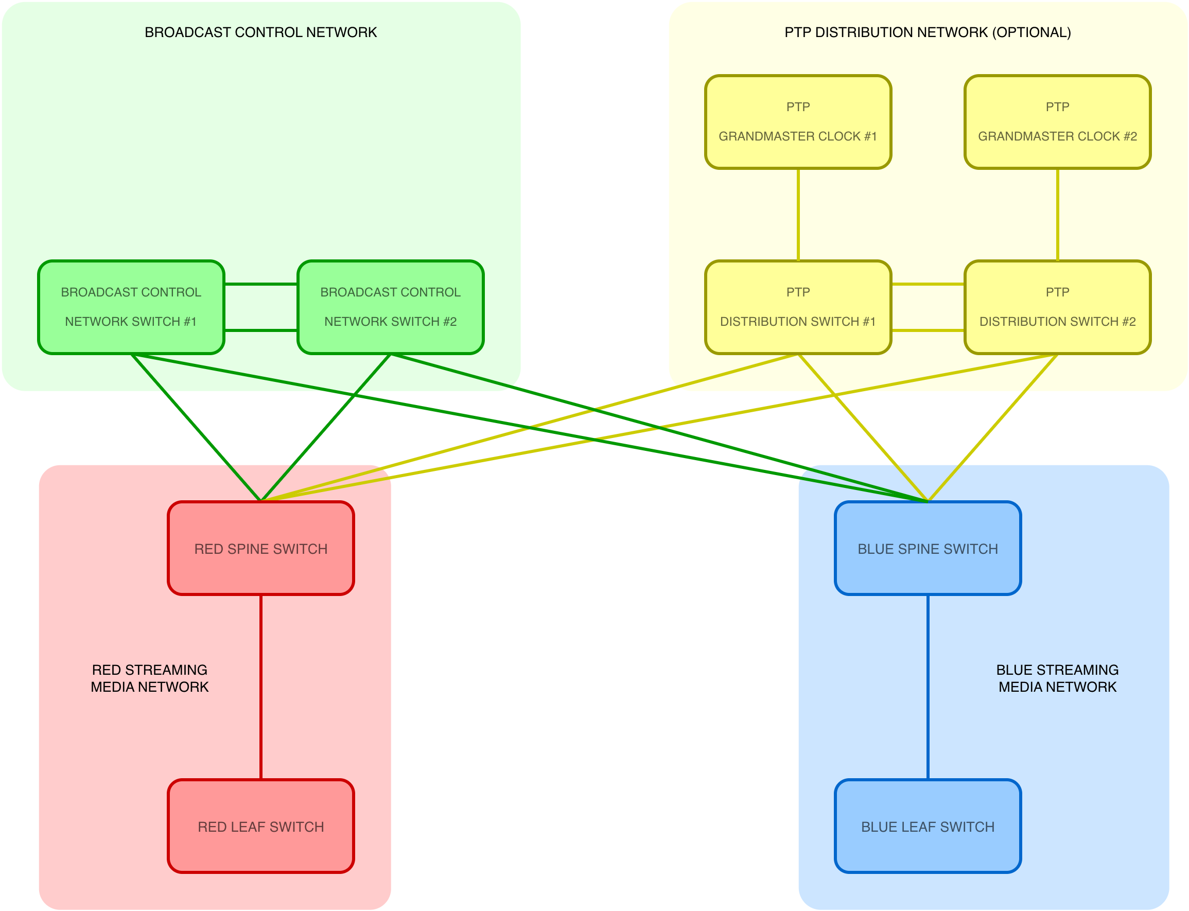
In SMPTE ST 2110 environments, PTP distribution can be implemented using dedicated timing distribution switches, integrated Broadcast Control switches, or directly through the Streaming Media networks. Each approach offers different advantages in terms of resilience, complexity and hardware requirements. Separating timing distribution from high-bandwidth media traffic can help protect critical synchronisation services from congestion, configuration changes and switch failures. However, this separation is an architectural choice rather than a requirement of ST 2110. Using a common timing reference helps maintain synchronisation between the RED and BLUE media fabrics. If the external reference is lost, the affected grandmaster clocks may enter holdover, maintaining their timebase using internal oscillators. The accuracy and duration of holdover depend on the capabilities of each clock. Where independent grandmasters operate in holdover, their clocks may gradually drift apart, potentially affecting alignment between redundant media streams.
Function
PTP distribution carries PTP messages as defined by SMPTE ST 2059-2 (the broadcast profile of IEEE 1588). This profile defines how PTP is used in professional media, including timing reference, message rates and alignment with video formats. Its key functions include:
- Distributing time from a PTP Grandmaster clock (GMC) to all media endpoints
- Maintaining sub-microsecond synchronisation accuracy
- Providing redundancy through multiple GMCs and BMCA (Best Master Clock Algorithm) enabling automatic failover if the active GMC fails
- Supporting 'Boundary Clocks' (BC) and/or 'Transparent Clocks' (TC) within network switches
- Boundary Clock: acts as a PTP follower on one interface and a PTP leader on downstream interfaces, effectively regenerating timing information (preferred for ST 2110)
- Transparent Clock: measures and corrects delay through the switch
- Isolating and protecting timing traffic from congestion and delay variation
- Operating within defined PTP domains, which allow multiple independent timing systems to coexist without interference
PTP Profile Basics (SMPTE ST 2059-2)
In SMPTE ST 2059-2, the behaviour of PTP is tightly defined to ensure consistent operation across all devices on an ST 2110 network. Some key parameters include:
- PTP Domain ID - a numerical identifier used to separate independent timing systems
- Message Rates - PTP uses regular timing messages (Announce, Sync, Delay-Request) sent at defined intervals. Higher message rates can improve accuracy, but also increase network load
- ST 2059-2 defines a common epoch and alignment to video frame boundaries
- Delay Mechanism - typically uses delay request-response to measure network path delay between devices and the GMC
Common PTP Profiles (Deployment Examples)
IEEE 1588-2008, AES67 & SMPTE ST 2059-2 Interop (common for audio-only deployments)
| Parameter | Typical Value |
|---|---|
| Domain | 0 |
| Announce Interval | 0 |
| Announce Timeout | 3 |
| Sync Interval | –3 |
| Delay-Request Interval | –3 |
AES67 & SMPTE ST 2059-2 Interop (common for video and audio deployments)
Common interoperability settings for mixed AES67 and SMPTE ST 2059-2 deployments, as recommended by AES-R16-2016.
| Parameter | Typical Value |
|---|---|
| Domain | 127* |
| Announce Interval | 0 |
| Announce Timeout | 3 |
| Sync Interval | –3 |
| Delay-Request Interval | –3 |
*Domain 127 is the default defined by SMPTE ST 2059-2, although other values may be used by agreement within a facility.
SMPTE ST 2059-2 (highest rate)
| Parameter | Typical Value |
|---|---|
| Domain | 127 |
| Announce Interval | –2 |
| Announce Timeout | 3 |
| Sync Interval | –3 |
| Delay-Request Interval | –3 |
PTP Message Rates
| Log Interval Value | Time Interval | Message Rate |
|---|---|---|
| 1 | 2 seconds | 1 message per 2 seconds |
| 0 | 1 second | 1 message per second |
| –1 | 0.5 seconds | 2 messages per second |
| –2 | 0.25 seconds | 4 messages per second |
| –3 | 0.125 seconds | 8 messages per second |
Hardware Support vs QoS
Accurate PTP distribution depends on both the capabilities of the network equipment and the conditions under which timing packets are transported. Switches with hardware-assisted PTP support can timestamp packets directly at the network interface, reducing the uncertainty associated with software-based timestamping. Depending on their implementation, switches may also operate as Boundary Clocks (BC) or Transparent Clocks (TC) to improve timing distribution across the network.
Quality of Service (QoS) provides a complementary mechanism by prioritising PTP traffic over less time-sensitive traffic, helping to reduce queuing delays and packet delay variation (PDV) during periods of network congestion. However, QoS alone cannot compensate for inaccurate timestamping or the absence of appropriate PTP hardware support. Similarly, hardware-assisted PTP does not eliminate the effects of network congestion. For this reason, reliable PTP distribution requires suitable hardware, appropriate QoS policies and careful network design.
Hardware-assisted PTP processing significantly reduces excessive jitter and cumulative timing errors compared to software-based forwarding (QoS). This directly impacts media alignment, system stability and scalability.
- Practical example: In certain implementations without hardware-assisted PTP processing, timing accuracy can begin to deteriorate at relatively modest network utilisation levels (approximately 20%). At higher utilisation levels (approximately 50%), packet delay variation may become sufficiently severe to compromise reliable synchronisation, even when QoS policies are configured
- These figures are illustrative of implementation-specific behaviour rather than universal thresholds. Actual PTP performance depends on the hardware architecture, traffic characteristics, QoS implementation and network design
RTP and PTP — Different Roles
A common misconception is that RTP and PTP perform the same function.
- RTP carries the media itself and provides packet sequence numbers and media timestamps.
- PTP distributes a highly accurate shared time reference across the facility.
- ST 2110 receivers use information from both protocols to correctly align and reconstruct video, audio and ANC streams.
In simple terms:
- RTP carries the content
- PTP tells devices what time it is
Why It Matters
In ST 2110 systems, timing is distributed separately 'over' the network. PTP enables:
- Frame-accurate switching
- Lip-sync integrity
- Audio phase coherence
- Clean ST 2022-7 stream reconstruction (ensuring both paths remain time-aligned)
- Predictable stream performance across a facility
Without stable PTP, the entire ST 2110 system becomes unstable, even if the media transport itself is functioning.
Optional Hardware Layer
A dedicated PTP Distribution network (separate hardware) is considered an optional architectural layer, not a protocol requirement. ST 2110 requires PTP for synchronisation, but it does not mandate that PTP must run on any specific network infrastructure. A separate PTP Distribution network can:
- Improve resilience
- Simplify fault-finding
- Isolate timing from media traffic
However, the increase in hardware cost and complexity can be difficult to justify, which is why it tends to be used in organisations with large networks. It is entirely feasible to integrate and distribute PTP without a physically separate network, provided the system is correctly engineered. Without accurate timing, receivers cannot correctly align streams, resulting in visible artefacts, audio distortion, or complete signal instability.
PTP Integration & Distribution - Summary
- PTP integration and distribution delivers a highly accurate and stable time reference throughout an entire ST 2110 facility
- Integrating PTP into an IP broadcast facility can be achieved via:
- The Broadcast Control network
- Directly to the Streaming Media networks
- Via dedicated network switches acting as a PTP Distribution network to the Streaming Media networks (optional, not mandatory)
- Each switch in the path of PTP distribution should ideally be configured as a Boundary Clock
- Switches should support PTP in hardware with QoS as a backup protection mechanism
- Use appropriate PTP domains to isolate systems where required
In the next chapter, the role and functions of the Broadcast Control network are explained with a view to describing how the various network fabrics communicate with each other to perform stream patching.