1. An Overview of Lawo Validated Networks
Introduction
LVNs are a portfolio of validated network architectures that can be combined to build complete IP broadcast facilities. The designs cover the following fabrics:
- Broadcast Control / Management networks
- PTP Integration and Distribution networks
- Streaming Media networks (audio and video)
- SDN Controlled networks
All Lawo Validated Networks (LVNs) follow the best practices of major network vendors in terms of topology design, unicast and multicast routing and the integration of timing/reference synchronisation. LVNs also provide a standardised approach to integrating Lawo product lines, ensuring optimal performance.
Customer Benefits
- LVNs are established on the best practices and experience Lawo has gained from deploying hundreds of IP projects across the globe
- LVNs follow the best practices of major network vendors
- LVNs simplify the process of choosing a network topology for specific applications
- LVNs prevent compromised levels of hardware and software redundancy
- LVNs provide a consistent architecture that is simple to understand and is applicable to both the Broadcast Control / Management and Streaming Media fabrics
- LVNs provide consistent and standardised configurations to understand and maintain across Spine and Leaf switches
- LVNs can be deployed as either 1-tier to multi-tier solutions
- LVNs are used internally at Lawo
Technical Benefits
- All Streaming Media LVNs are ‘hybrid’ by default
- Hybrid denotes the ability to connect endpoints either directly to Spine switches or via Leaf switches within the same architecture
- LVNs can increase the scale of a network as standard without impacting unicast or multicast performance
- LVNs have redundancy strategies for hardware/cable failures and protection against network disruption and multicast flooding
- LVN designs increase the ability to identify and troubleshoot issues
- LVN designs are a collaborative effort between Lawo and major network vendors
- Technical implementation guidelines and configuration examples are available as supporting documentation within an LVN solution
Validation Criteria
An LVN has been:
- Lab tested by Lawo
- Tested with supported Lawo products
- Reviewed against vendor best practices
- Supported by implementation documentation
Validation does not imply certification of every possible hardware combination, software release or customer-specific topology variation An LVN is not intended to be a fixed network design. Instead, it provides a validated architectural foundation based on industry best practices, proven deployment experience and tested integration patterns. LVNs establish the core design principles for broadcast control, media transport, timing distribution and network resilience while allowing the remaining aspects of the solution to be adapted to customer-specific operational, commercial and technical requirements.
LVN Design Philosophy
Every LVN is designed around four principles:
Predictability
- Consistent behaviour
- Predictable forwarding
- Well-defined failure domains
Resilience
- Hardware redundancy
- Link redundancy
- Multicast protection
Scalability
- Expand without redesign
- Support incremental growth
Operational Simplicity
- Repeatable deployments
- Standardised configurations
- Simplified troubleshooting
LVN Design Principles
At their core, LVNs are variations based on a ‘Spine-Leaf’ or ‘Clos’ network architecture. The design incorporates two tiers of network hardware per fabric:
- Spine - the core switches of the network that performs switching and routing traffic between the endpoints, networks and Leaf switches
- All the Leaf switches in the fabric connect to the Spine
- Leaf - the access switches that typically connect the endpoints to the fabric - e.g.
- PCs, servers, IP processors, audio/video gateways, cameras, control panels, consoles etc.
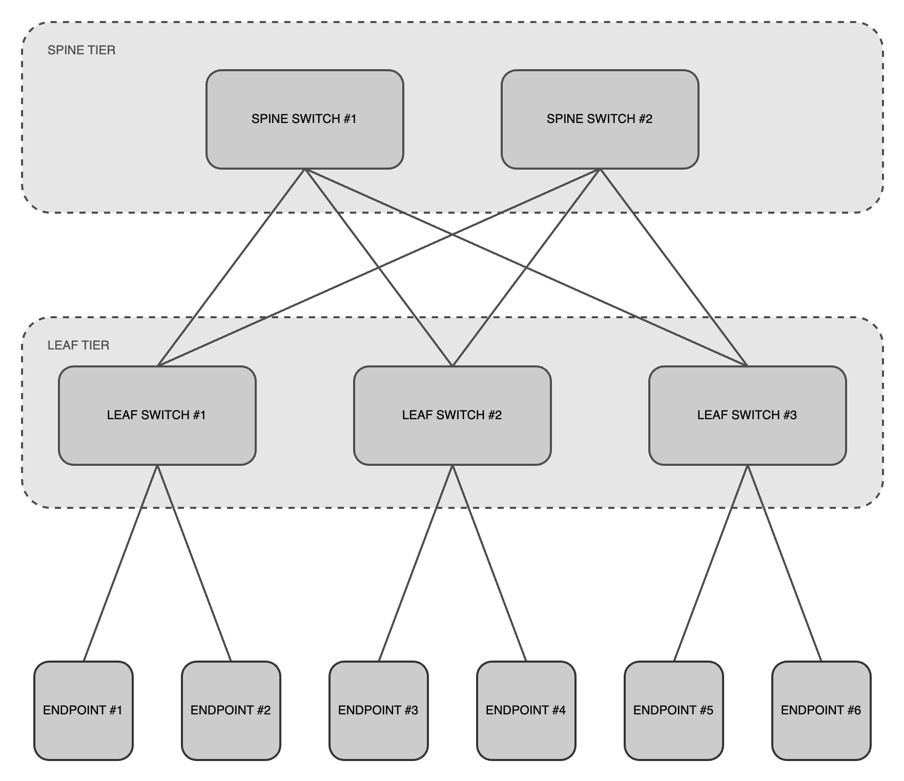
LVNs are expandable solutions, for example: the Spine tier could be deployed first as part of a single tier solution or project phase. When network capacity is required to increase, the Leaf tier can be added at a later date.
Benefits of a Spine-Leaf Design
Spine-Leaf topologies are suitable for modern IP broadcast facilities as they offer the following benefits:
- High Availability (HA)
- The ability to tolerate failures and remain operational/accessible with minimal downtime. This is achieved by implementing multiple redundancy strategies;
- Multiple Spine switches provide protection against failures, whereby traffic is forwarded via the remaining active Spine switch without impacting connectivity
- The specific number of Spine switches supported depends on the selected LVN design and validated deployment architecture
- Multiple uplink connections between endpoints and switches provide additional network paths between devices
- Therefore the network remains operational even if individual links or switches fail, as traffic can be forwarded via alternate paths
- NOTE - Streaming Media topologies can be deployed with HA (e.g. SMPTE 2022-7 SPS Red and Blue networks) or without HA (e.g. Red network only)
- Multiple Spine switches provide protection against failures, whereby traffic is forwarded via the remaining active Spine switch without impacting connectivity
- The ability to tolerate failures and remain operational/accessible with minimal downtime. This is achieved by implementing multiple redundancy strategies;
- Scalability
- The ability to increase network capacity without major disruption or downtime - e.g. adding more Leaf switches
- Spine-Leaf architectures can scale to very large deployments. The practical scale of an LVN deployment depends on the selected design, hardware platform and validated architecture
- Simplified Troubleshooting and Management
- A consistent, uniform layout which makes it easier to diagnose and resolve issues
- The symmetrical design removes complexity from planning, configuration and management
- Automation
- The ability to automate infrastructure to rapidly and safely implement changes based on requirements
It is common to find Spine-Leaf networks in data centers, cloud service providers, high performance computing (HPC) environments and content delivery networks (CDNs). Additional benefits that can be leveraged for broadcast media applications are:
- Non-blocking
- Denotes the capability for all network interfaces to operate at full bandwidth capacity (TX and RX) without dropping packets or suffering signal disruption
- This is achieved by providing sufficient uplink capacity (from the Leaf to the Spine) to match or exceed the downlink capacity (from endpoints to Spine/Leaf switches)
- NOTE - in the event of an uplink failure, Streaming Media Spine-Leaf topologies can become blocking
- In blocking topologies, Software-Defined Networking (SDN) solutions such as Arista Media Control Service (MCS) and Cisco Nexus Dashboard Fabric Controller (NDFC) can manage multicast traffic
- NOTE - in the event of an uplink failure, Streaming Media Spine-Leaf topologies can become blocking
- Predictable, low latency
- Traffic between any two endpoints typically passes through a maximum number of hops - e.g. Leaf switch → Spine switch → Leaf switch - with a consistent number of uplinks and bandwidth
- Therefore each endpoint has equal access to all other endpoints
- This approach reduces latency and ensures optimal performance for real-time applications such as audio and video streams
- High throughput
- When a Spine-Leaf architecture is deployed using switch hardware that is internally non-blocking, the network is capable of very high throughput
- Streaming Media networks typically utilise hardware platforms with interface speeds of:
- 1/10G for audio switch downlinks
- 10/25G for audio switch uplinks
- 25/40/50/100G for video switch downlinks
- 100G/400G for video switch uplinks
- This ensures audio, video and control data can be forwarded efficiently and without bottlenecks, even in environments with heavy traffic loads
- Streaming Media networks typically utilise hardware platforms with interface speeds of:
- When a Spine-Leaf architecture is deployed using switch hardware that is internally non-blocking, the network is capable of very high throughput
- East-West traffic
- Modern applications (particularly streaming media devices) generate significant east-to-west network traffic (server-to-server communication). The Spine-Leaf architecture is designed to efficiently handle such traffic patterns, unlike traditional network architectures that focus more on north-south traffic (client-to-server)
LVN Portfolio Overview
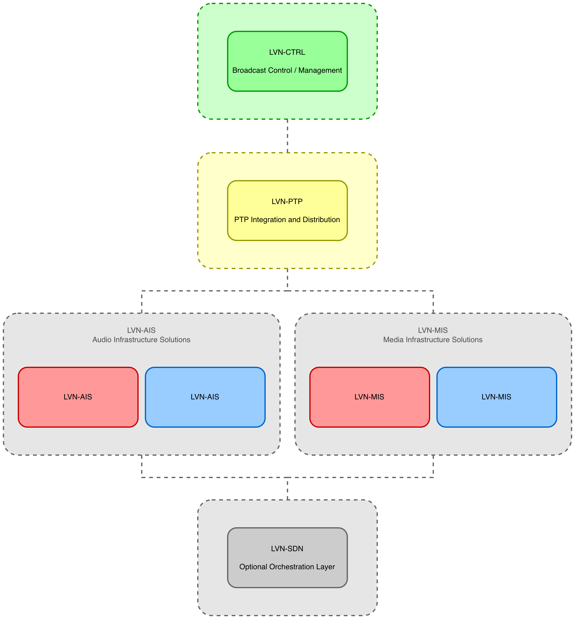
Lawo Validated Networks (LVNs) are a portfolio of validated network architectures designed specifically for IP-based broadcast, media and entertainment applications. Each LVN defines a standardised approach to topology design, routing, multicast distribution, timing integration and system resiliency. Rather than treating a facility as a single network, LVNs divide the infrastructure into several architectural domains, each optimised for a specific purpose. These validated architectures can be deployed individually or combined to form complete broadcast facilities of varying size and complexity.
The current LVN portfolio consists of five architecture families:
| LVN | Purpose |
|---|---|
| LVN-CTRL | Broadcast Control and Management networks |
| LVN-AIS | Audio Infrastructure Solutions |
| LVN-MIS | Media Infrastructure Solutions (video and audio) |
| LVN-PTP | PTP Integration and Distribution |
| LVN-SDN | Software Defined Networking and multicast orchestration |
Together, these architectures provide a consistent framework for designing, deploying and operating modern IP broadcast facilities.
LVN-CTRL
LVN-CTRL architectures provide the Broadcast Control and Management network used by systems such as:
- HOME
- VSM
- Monitoring systems
- Automation and orchestration systems
LVN-CTRL designs prioritise operational simplicity, availability and interoperability while providing the foundation for control-plane communication throughout the facility.
Available architectures:
| Architecture | Description |
|---|---|
| LVN-CTRL-1T | Single-tier active-active control network |
| LVN-CTRL-2T | Two-tier active-active control network |
LVN-AIS
LVN-AIS architectures are optimised for audio-centric environments where bandwidth requirements are typically lower than video-based deployments.
Typical applications include:
- Audio production environments
- Radio facilities
- AES67 deployments
- RAVENNA deployments
Available architectures:
| Architecture | Description |
|---|---|
| LVN-AIS-1T | Single-tier audio network |
| LVN-AIS-2T | Two-tier audio network |
| LVN-AIS-L2C-1T | Single-tier converged Layer 2 audio and control network |
| LVN-AIS-L2C-2T | Two-tier converged Layer 2 audio and control network |
LVN-MIS
LVN-MIS architectures are designed for high-bandwidth SMPTE ST 2110 video environments and form the Streaming Media network within a facility.
Typical applications include:
- Television studios
- Production facilities
- OB trucks
- Multi-studio campuses
Available architectures:
| Architecture | Description |
|---|---|
| LVN-MIS-1T | Single-tier media network |
| LVN-MIS-2T | Two-tier media network |
LVN-PTP
LVN-PTP architectures define validated methods for distributing timing and synchronisation throughout an IP broadcast facility.
Architectures are available for:
- Broadcast Control network integration
- Streaming Media network integration
- Dedicated timing distribution networks
Available architectures:
| Architecture | Description |
|---|---|
| LVN-PTP-CTRL-S | PTP via Broadcast Control network (single engine) |
| LVN-PTP-CTRL-R | PTP via Broadcast Control network (redundant engine) |
| LVN-PTP-MEDIA-S | PTP via Streaming Media networks (single engine) |
| LVN-PTP-MEDIA-R | PTP via Streaming Media networks (redundant engine) |
| LVN-PTP-DED-S | Dedicated PTP distribution network (single engine) |
| LVN-PTP-DED-R | Dedicated PTP distribution network (redundant engine) |
LVN-SDN
LVN-SDN architectures provide centralised control of multicast traffic and network resources using Software-Defined Networking principles. These architectures can simplify multicast deployment and improve operational visibility and security within large-scale media networks.
Available architectures:
| Architecture | Description |
|---|---|
| LVN-SDN-MCS | Arista MCS and CVX orchestration |
LVN Portfolio Diagram
LVN Roadmap
The LVN portfolio will continue to evolve as new network technologies, multicast architectures and broadcast workflows emerge.
LVN Design Applications
LVNs apply the benefits of a Spine-Leaf design to Broadcast Control / Management and Streaming Media networks, albeit with some key differences regarding the emphasis of using Layer 2 and Layer 3 technologies:
Layer 2 Spine-Leaf Networks (L2-SL)
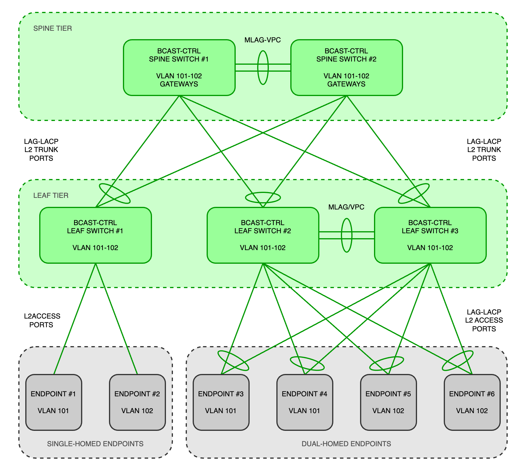
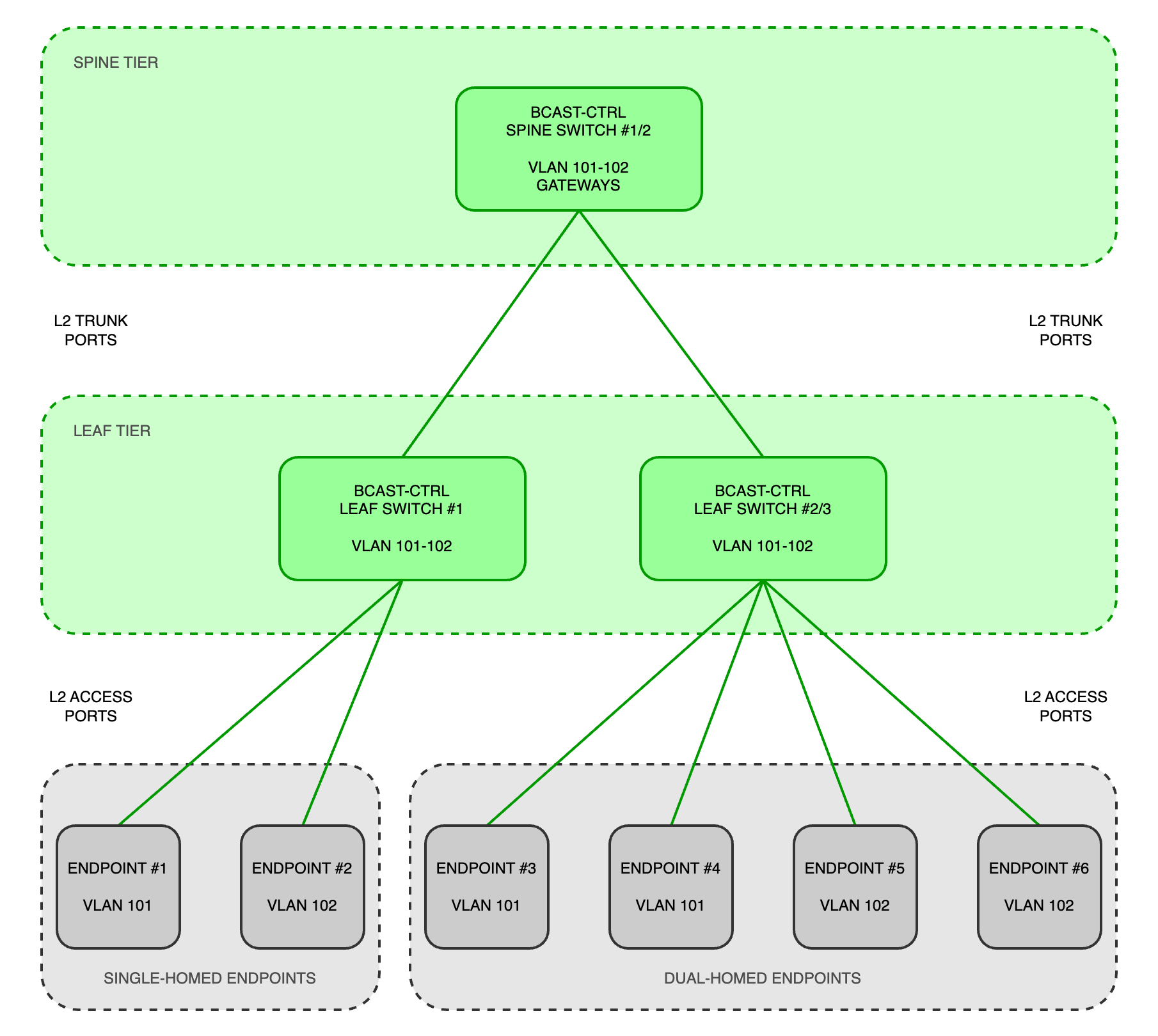
L2-SL topologies provide a simple design to understand and manage. Each Leaf switch connects to each Spine switch via a Layer 2 uplink, typically configured as a trunk port. The network can be organised by using 802.1Q VLANs which span across multiple switches in the Broadcast Control fabric, allowing for easy and dynamic movement of endpoints between switches. Endpoints connect to the network via Layer 2 access ports and all gateways and routing functions are performed by the Spine switches.
Additionally, Layer 2 aggregation technologies can be used to:
- Present two physically independent switches as one logical switch to the fabric - e.g.
- Multi-chassis Link Aggregation Protocol (MLAG)
- Virtual Port-Channel (VPC)
- Combine multiple physical network connections into one logical network connection - e.g.
- Link Aggregation Protocol (LAG)
- Link Aggregation Control Protocol (LACP)
This approach provides the ability to create ‘active-active’ connections between endpoints and switch uplinks to offer maximum network bandwidth by mitigating Spanning-Tree Protocol (STP) from placing certain ports in a blocking state to prevent network loops.
L2-SL networks are suitable for:
- Broadcast Control / Management networks
- Hypervisor platforms and virtual machine applications
- Containerised applications - e.g. HOME Apps
- Microservice applications - e.g. HOME
- Single-homed endpoints - e.g. vsmStudio hardware panels
- Dual-homed endpoints - e.g. A__UHD Core, HOME and HOME App servers, Power Core etc. (Broadcast Control / Management ports only)
- Devices that support network interface bonding/teaming

NOTE
Lawo does not recommend using Layer 2 Spine-Leaf designs for Streaming Media networksLayer 3 Spine-Leaf Networks (L3-SL)
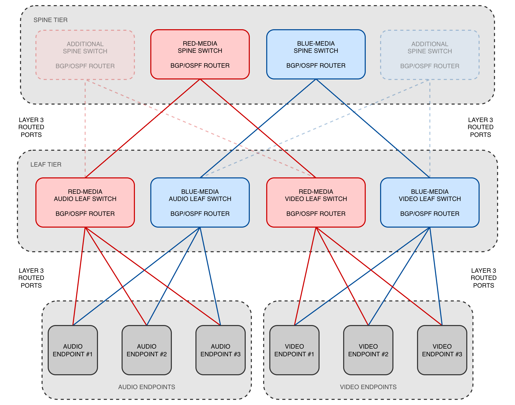
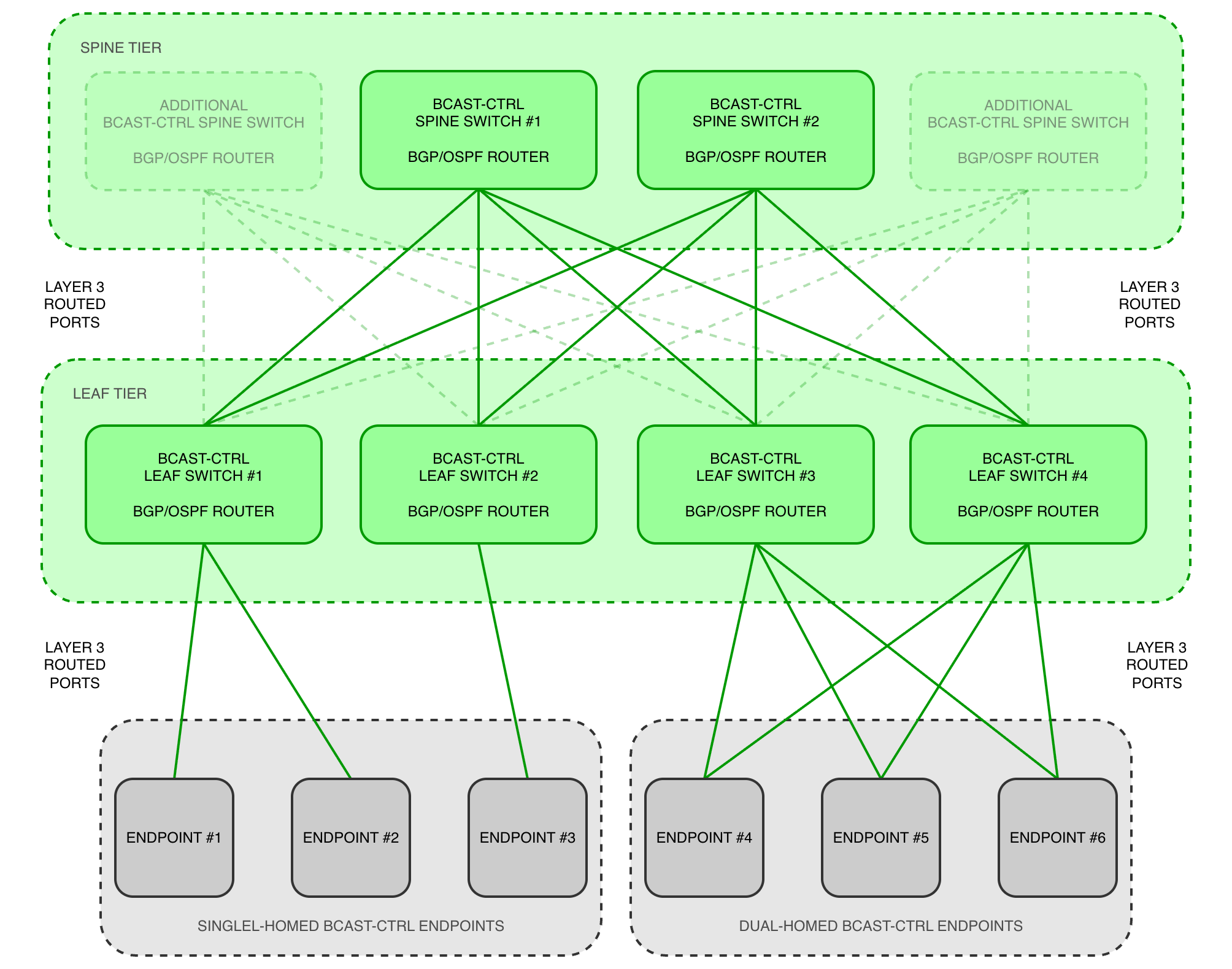
Layer 3 Spine-Leaf (L3-SL) topologies use routed connections between Spine and Leaf switches, providing greater isolation between network segments and reducing the size of Layer 2 failure domains. Each Leaf switch connects to the Spine tier using Layer 3 interfaces, typically configured with point-to-point IP addressing such as /30 or /31 networks. These connections provide dedicated routed paths between switches without extending Layer 2 broadcast domains across the fabric. Endpoints connect to the network through interfaces or VLANs associated with the appropriate IP subnet. Their default gateway is typically provided by the local Leaf switch, allowing traffic to be routed between endpoint networks. By limiting Layer 2 domains to the network edge and using routed connections throughout the fabric, L3-SL architectures help contain network faults and reduce the risk of Layer 2 loops and unwanted multicast flooding propagating across the wider infrastructure.
Using routed interfaces between endpoints and switch interfaces helps to isolate network issues to a single interface, preventing any fault or multicast flooding from propagating throughout the local switch and the entire fabric. L3-SL topologies also make extensive use of dynamic unicast routing protocols such as BGP/OSPF to advertise networks and route unicast traffic between networks, switches and endpoints. The default gateway for each endpoint is typically provided by the local switch. This means all Spine and Leaf switches participate in the routing of unicast and multicast traffic.
While this design introduces complexity, it also offers the following benefits:
- Eliminating the risk of network loops and Spanning-Tree Protocol (STP) placing ports into a block state
- More predictable failover and recovery mechanisms than Layer 2 designs
- Provision of the fastest re-convergence times after network disruption or failure
For Streaming Media networks, Protocol-Independent Multicast Sparse Mode (PIM-SM) is configured to efficiently route multicast streams between networks and switches with support for IGMP-based (version 2 or 3) or SDN-controlled multicast.
L3-SL networks are suitable for:
- Streaming Media networks
- PIM routed
- SDN controlled
- Advanced Broadcast Control / Management networks
- Topologies which require than two Spine switches per fabric
- VXLAN workflows (spanning a Layer 2 network over a WAN)
- EXAMPLE L3 SPINE-LEAF STREAMING MEDIA NETWORK
- EXAMPLE L3 SPINE-LEAF BROADCAST CONTROL / MANAGEMENT NETWORK
Deploying LVNs
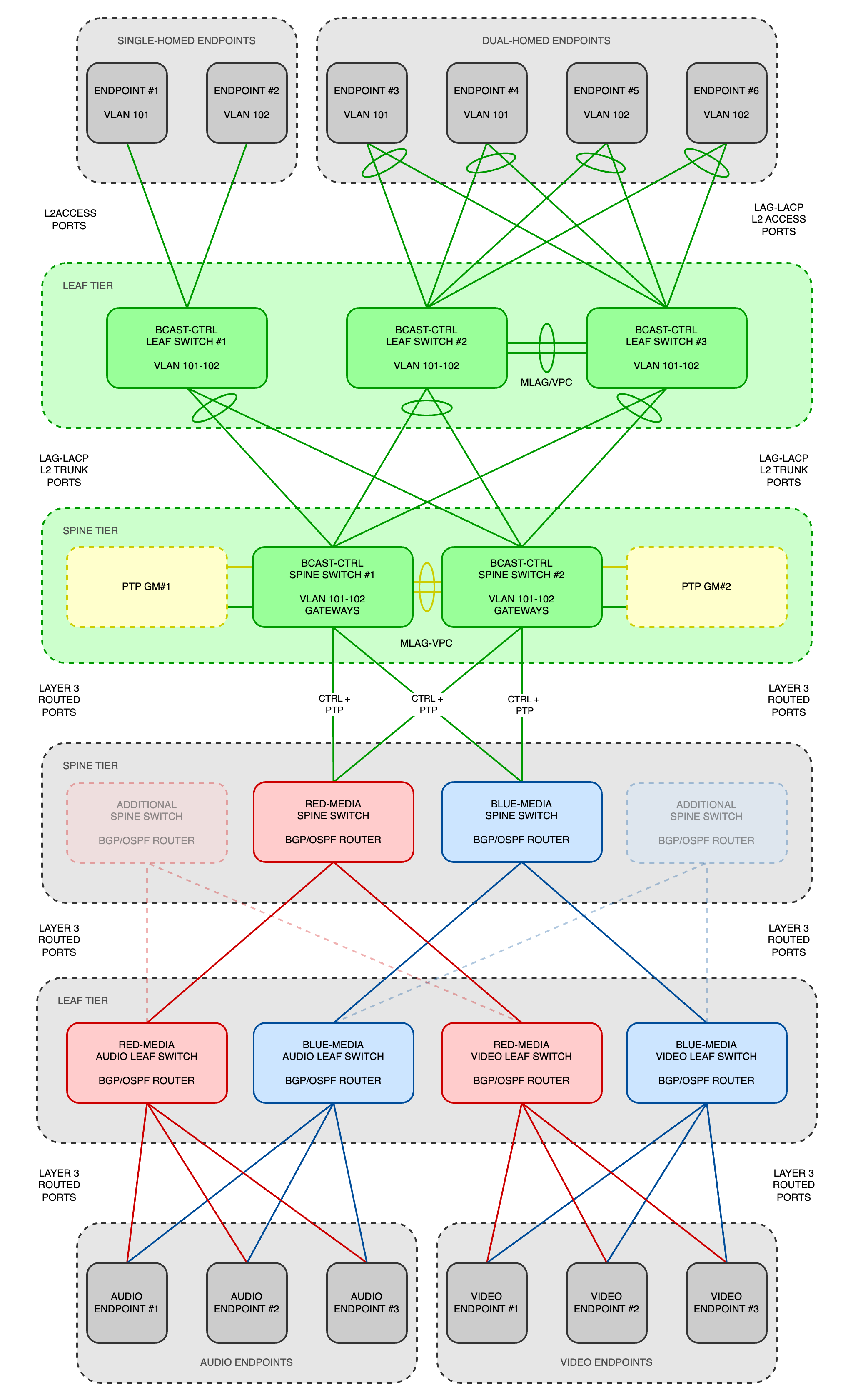
All LVNs can be treated as a set of components that integrate together to form a customised network topology, consisting of Broadcast Control / Management and Streaming Media fabrics with PTP Integration/Distribution.
Example deployment of multiple LVNs
How LVNs Are Delivered
LVNs can be adopted at different levels depending on customer requirements. Some organisations use LVNs as design guidance during planning, while others engage Lawo Professional Services or Lawo partners to assist with implementation, validation and operational readiness.
Supporting documentation includes:
- Reference architectures
- Configuration examples
- Design guidance
- Validation procedures
- Best-practice recommendations
Contact your local Lawo sales representative for more information regarding Lawo Validated Networks, including:
- Specific designs and technical details from the wider portfolio
- How your organisation can take advantage of LVNs
- The full range of available network services Lawo can provide